• Scam Alert. Members are reminded to NOT send money to buy anything. Don't buy things remote and have it shipped - go get it yourself, pay in person, and take your equipment with you. Scammers have burned people on this forum. Urgency, secrecy, excuses, selling for friend, newish members, FUD, are RED FLAGS. A video conference call is not adequate assurance. Face to face interactions are required. Please report suspicions to the forum admins. Stay Safe - anyone can get scammed.

Tips/Techniques Mill Tramming Question

Tips/Techniques

whydontu

I Tried, It Broke
Premium Member
So I've trammed my new RF30 mill, and I have a question on the validity of my results.

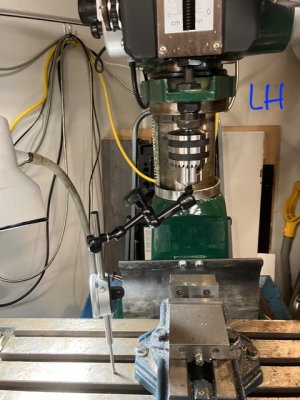
I installed a three-axis DRO, and confirmed the axis calibration by chucking a 2" throw dial indicator in a drill chuck. Zeroed the dial indicator at end of travel against the table, zeroed the DRO, and extended the quill 2.000" as read on the dial indicator. Confirmed DRO read 2.000" travel.

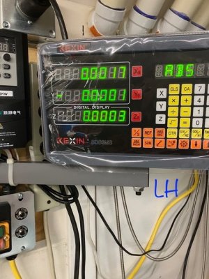
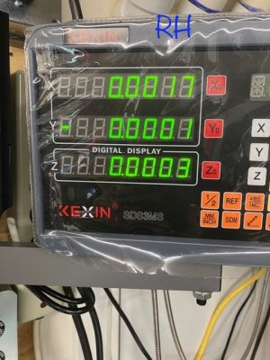
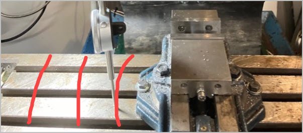
So today I chucked the same 2" throw dial indicator in a holder, zeroed it with about 0.200" of quilll extension, with the tip placed as far to the right as I could, zeroed the DRO. Moved the quill up and down to the zero point, DRO reads 0.0003", so I know the DRO is active and that's within the 5 micro resolution. Lifted the quill so the dial indicator wasn't touching the table, and spun the quill 180* without touching the dial indicator or chuck (spun it using the spindle pulley). Extended the quill to the same zero point at 0.200" extensions, and compared the DRO reading. DRO read the same 0.0003".

Is this a valid way to check tram? If I try to spin the quill with the dial indicator touching the table it twists and goes out of true.

IMG_4226.jpeg
IMG_4227.jpeg
IMG_4229.jpeg
 

Attachments

  • IMG_4230.jpeg
    IMG_4230.jpeg
    92.8 KB · Views: 7
  • IMG_4231.jpeg
    IMG_4231.jpeg
    77.8 KB · Views: 7
  • IMG_4227.jpeg
    IMG_4227.jpeg
    76.3 KB · Views: 6
Last edited:
Sounds legit to me. the only other thing you could do to be more precise is remove the vise and eliminate the need to raise the quill between measurements. When rotating between RH and LH I just lift the indicator tip a wee bit to clear the T slots.
 
Sounds fine, Technically I guess it would be better to not move the Z, but at that distance of sweep any amount out would be microcscopic at the diameter of a normal sized cutter

Just for convenience, try putting a parallel or 123 block under the indicator point. Read and remove the block. Then when rotating the spindle the indicator isn't touching anything, and also can't foul in the T slots.
 
The numbers are encouragingly small so probably not an issue. By introducing a second measurement device (the DRO) into the collective mix, technically you now have 2 potential sources of resolution/repeatability deviation in the mix. Maybe you did this step prior & already trust the DRO within its limits. But for example if you had a high(er) resolution DTI like 0.00000" and you didn't do any nod/tram swinging at all, you just repeatedly raised & lowered the knee & evaluated resultant DRO display when the DTI read same null/zero & got DRO values like +0.0004, 0.0002, -0.0003., 0.0001, -0.0004.. then worst case your DRO repeatability would be the min/max of these values ABS(+0.0004,-0.0004) = 0.0008". Or one could argue, throw away the outliers. Or one could argue some other averaging / distribution based method. The point is that second DRO devise measurement variation should be considered when you now do a new positional move where both instruments are telling you a number, like rotating the arm to a new position. Are you measuring the tilt or are seeing the slop in instrumentation?

For the purpose of spindle/table setup it would be better to just get the vise out of the way so you can measure tilt/nod using the same (one) DTI which is always loaded in the same manner. You could increase accuracy by extending the arm outward L/R, but you are limited in in/out by the table width unless you use a parallel to extend the measurement positioned the exact same way.

Step 2: Now with the nod/tilt (mill spindle/table relationship) all as satisfactory as possible, don't forget to evaluate the vise itself. Well, at least once when it was new & also occasionally as sanity check for dings & debris. For most people 80% of their work involves holding in the vise. So if it happens to be canted 0.001" in some off-direction to an otherwise perfect table/spindle relationship, then IT introduces its own nod/tilt discrepancy relative to part machining.
 

Attachments

  • EDT-27-09-2024 10.47.46 PM.jpg
    EDT-27-09-2024 10.47.46 PM.jpg
    34.3 KB · Views: 1
Last edited:
@whydontu - I made a really nice tramming fixture out of a vehicle brake disk. If desired, the disk can be lifted above the mill table to clear a vise by setting it on three known good 123 blocks. I needed 246 blocks to clear my vise so I used my surface grinder to make three custom blocks ground simultaneously instead.

Brake Disks are manufactured to extremely tight tolerances to eliminate brake pedal pulsing. The one I used had no measureable runout on the various devices I used to measure it with. 12" Disks are common but larger are also available. I used 12.

By centering the disk under the spindle you can extend measurements behind and in front of the table. You also achieve a continuous sweep without needing to worry about T-slots. The disk facilitates both nod and x/y tramming.

There is a thread that describes what I did that starts here:

Post in thread 'Spindle square' https://canadianhobbymetalworkers.com/threads/spindle-square.4225/post-56538

I didn't make the indicator fixture I discussed there yet, but there is enough detail in the reference thread to allow you to fully tram your mill with ease. It was an interesting thread and I enjoyed the learning it provided.
 
Back
Top