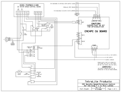
My BB CT129 milling machine uses a 90 volt DC motor with a KBIC-120 variable speed control. Speed is set using a simple rotary pot. There is an auxiliary input that stops the motor without disconnecting power to the speed control.
My last project was to build a non-contact tachometer with a simple microcontroller that lets me dial-in the cutter size and then the microcontroller calculates the SFM speed based on the cutter RPM.
Doing a deeper dive into the KBIC-120 owners manual, I discovered the motor speed can be adjusted by an external 0 to 7 volt dc signal.
The new project will modify the tachometer to combine it with the speed control function.
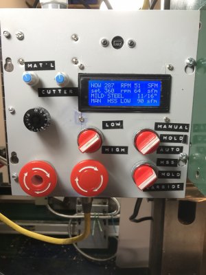
Dial #1 to select workpiece material
Dial #2 to select cutter size
Dial #3 to set cutter RPM for manual operation
Off / Manual / Automatic switch with indicator lights
Big red STOP button that stops the spindle but leaves all the settings intact
Even bigger red STOP button that shuts off everything
LCD display, 20 characters wide x 4 rows high
All in an 8”x8” metal enclosure
in use, the controller will display material, cutter size, recommended SFM based on Machinists Handbook charts, recommended RPM based on these three bits of information, and actual cutter RPM. In Manual mode, dial #3 will adjust motor speed. In Automatic mode the controller will adjust cutter speed by software, ignore dial #3, and output a proportional 0-7 volt signal to the motor speed controller. Automatic mode will be closed-loop feedback to maintain proper RPM by comparing calculated RPM setting to actual spindle RPM.
The display will look like this:
Mat’l: ALUMINUM
Cutter Dia.: 11/16”
RPM: 300 SFM: 50
Spindle RPM: 280
I‘m about 20% along the way. I’ve breadboarded the microcontroller, written software for the display and tachometer functions. Next tricky step is to write the automatic functionality. Then bench test, fix bugs, make the enclosure for all the sub-assemblies, and engrave a new front panel. Maybe $200 total in parts, including the enclosure.
When and if I get this all working I’ll post more info.
FYI - most VFDs will accept a 4-20mA proportional control signal to adjust motor RPM. With one component change the microcontroller can easily be modified to produce this type of signal.


