• Scam Alert. Members are reminded to NOT send money to buy anything. Don't buy things remote and have it shipped - go get it yourself, pay in person, and take your equipment with you. Scammers have burned people on this forum. Urgency, secrecy, excuses, selling for friend, newish members, FUD, are RED FLAGS. A video conference call is not adequate assurance. Face to face interactions are required. Please report suspicions to the forum admins. Stay Safe - anyone can get scammed.

Mill Quill stop

Ironman

Ultra Member
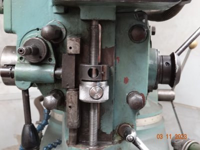
Repeated hole drilling to a set depth means twiddling with the stop collars on the mill for 5 minutes til you get it where you want it, and then doing it all over again when you want full stroke. So I made myself a push button quick lock setup. The thread on the depth stop is 12x1mm, of course I had to order a tap
I started sifting through all the stub ends from projects completed in the past. Needed a short bit of 1.75 CR and a piece of 3/4" stock.
It's hard to believe, but I don't have one. So a stub of 1" had to be turned down.
I found a little bit of 1.75", barely enough to grab in the chuck as there was a bit of whittling to do. I managed to machine away the damages on it, almost...and then knurled it. Flipped it around in the jaws and grabbed the knurled end with some pop can shims to protect the knurl, and bored it to 12mm. Then I could stabilize with the live center, and machine the collar that goes up into the quill block.

Now the fun part. I have to bore a hole into it for the half nut button thing, and make some relief for a spring, all without punching through the other side.
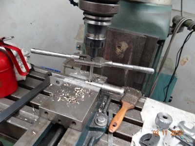
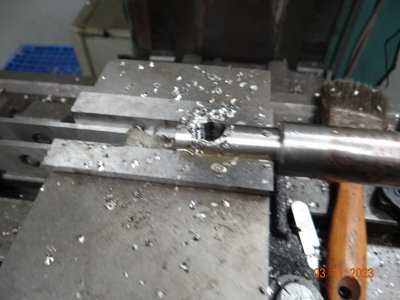
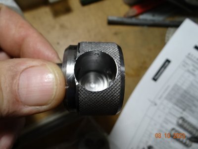
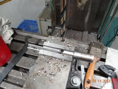
I'm sure there is a proper way to do this, but lacking the know how, I drew it out on the plasma program to scale, and made .100 as my safety margin to breakthrough. I measured the depth on the screen, and then used a 3/4" end mill to drill down the required depth, and it worked. Then I threaded the stock that will be my button, and as in the 3rd picture, I moved over and used a 1/2 endmill to punch out space for the threaded rod when disengaged. It took a little filing and fiddling til I had a smooth transition from thread engaged to disengaged position.
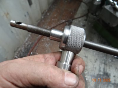
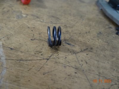
Picture 4 shows a test assembly of the gizmo. In #5, I had to find a spring the right size and cut it and pull some temper so it was not too stiff. The spring fits in the hole shown in #6, then the threaded rod slides in and the spring pushes the half nut into the rod to engage. Push the button in to disengage the halfnut and slide it to where you want it.
It works fine. My explanation may be a bit lacking....
 

Attachments

  • DSC05258.JPG
    DSC05258.JPG
    410.7 KB · Views: 25
  • DSC05259.JPG
    DSC05259.JPG
    332.2 KB · Views: 22
  • DSC05261.JPG
    DSC05261.JPG
    277.4 KB · Views: 21
  • DSC05263.JPG
    DSC05263.JPG
    205.7 KB · Views: 20
  • DSC05265.JPG
    DSC05265.JPG
    200 KB · Views: 20
  • DSC05250.JPG
    DSC05250.JPG
    209.3 KB · Views: 21
  • DSC05264.JPG
    DSC05264.JPG
    307.5 KB · Views: 24
I've had making one of on my to do wish list for a while, nice job!

D :cool:
Well done.
My mill "had" the same 12x1mm rod as yours but rather than order a tap I turned a new rod with 1/2 -20 tread then ordered a cheap clamp style stop.
I searched as well and never found a stop with the metric thread.
The thing with the 1mm thread is each turn of the nut is 1 mm, 1/2 turn...you get the picture. For fine critical depth setting. At first I was going to go your route, but thinking about it, I wanted the fine adjustment ability. The 12x1 tap and accompanying die was 15 bucks free ship from china. As I procrastinated for many years to get this done, a 2 week wait from china was ok.
As far as your ToDo list, this is a simple under 2 hr job with this design. Some others I have seen are more complex, and cannot be rotated to fine adjust the depth. There is no critical measurements, and the hardest part for me was finding the right spring in my spring jar, and fine tuning it.
 
I've looked at the button type but haven't been willing to pay the price. Now that I see how they're built I think I'll build one as well still with the 1/2-20 as I don't have the metric tooling. With my mill I'll be able to get close to 180 degrees of adjustment which is double what I get with the clamp style.

Thanks for posting.
 
I happened to be ordering a bunch of parts already from H&W, but I included this one in my order and it works a treat.

 
Gotta luv inspiration, spent a few hours in the shop over the last couple of days and look what happened.
View attachment 33127
The button might be a bit long but it makes a good handle. lol
Well, hell, look at that.:)
If you want to shave down the button, you could rotate it for fine adjustment, but you know that.
It's a pretty easy project to make.
 
I can get over 180 degrees of travel with the button the way it is and that gives me 0.025 of adjustment which isn't bad, but I think I'll cut it down to have the full 0.050 adjustment.
And you're right, it is a fairly easy project.
 
Repeated hole drilling to a set depth means twiddling with the stop collars on the mill for 5 minutes til you get it where you want it, and then doing it all over again when you want full stroke. So I made myself a push button quick lock setup. The thread on the depth stop is 12x1mm, of course I had to order a tap
I started sifting through all the stub ends from projects completed in the past. Needed a short bit of 1.75 CR and a piece of 3/4" stock.
It's hard to believe, but I don't have one. So a stub of 1" had to be turned down.
I found a little bit of 1.75", barely enough to grab in the chuck as there was a bit of whittling to do. I managed to machine away the damages on it, almost...and then knurled it. Flipped it around in the jaws and grabbed the knurled end with some pop can shims to protect the knurl, and bored it to 12mm. Then I could stabilize with the live center, and machine the collar that goes up into the quill block.

Now the fun part. I have to bore a hole into it for the half nut button thing, and make some relief for a spring, all without punching through the other side.
I'm sure there is a proper way to do this, but lacking the know how, I drew it out on the plasma program to scale, and made .100 as my safety margin to breakthrough. I measured the depth on the screen, and then used a 3/4" end mill to drill down the required depth, and it worked. Then I threaded the stock that will be my button, and as in the 3rd picture, I moved over and used a 1/2 endmill to punch out space for the threaded rod when disengaged. It took a little filing and fiddling til I had a smooth transition from thread engaged to disengaged position.
Picture 4 shows a test assembly of the gizmo. In #5, I had to find a spring the right size and cut it and pull some temper so it was not too stiff. The spring fits in the hole shown in #6, then the threaded rod slides in and the spring pushes the half nut into the rod to engage. Push the button in to disengage the halfnut and slide it to where you want it.
It works fine. My explanation may be a bit lacking....

Nice. I need this for our mill.

I happen to be working on the DRO mount for the quill depth today and will plan this at the same time.
 
I have an old Delta drill press that had one of those 1/2 -13 push button stops on it. I built a stop into the mount I made for a quill DRO I put on the lathe mill combo I recently sold. At that time I did a search using the part number for the push button stop nut on the drill press and found a place that sold them at a very good price. I think I bought 2. When I put the 3 axis DRO on my mill I was going to build a stop into the mount but just couldn't find room to fit it in. Now I just set the depth I want on the DRO and use that so I don't think I would bother with the stop. I should look around a see if I still have that 2nd stop nut I bought.
 
Nice. I need this for our mill.

I happen to be working on the DRO mount for the quill depth today and will plan this at the same time.

Good idea. I did my quill DRO before I saw this gizmo that @YotaBota did. Now I'm not sure I can. One thing to note is that taking the quill stop apart on a BP is not a slam dunk. Another reason to plan them together.

It's project 42k.

Here is a link to the start of the quill part of my mill DRO system thread. Works awesome with my table height DRO.

Post in thread 'Installing a DRO on a Hartford Bridgeport Clone.' https://canadianhobbymetalworkers.c...n-a-hartford-bridgeport-clone.4852/post-85016
I guess that is one way to do it :p

I spent 1/2 an hour this afternoon working out how I wanted to tackle the quill scale for the DRO. I wanted unobtrusive, compact, non-interference fit. I also wanted to have minimal modification of the mill. I've figured out a way that should have great alignment, yet allows for potential misalignment, and that can be accomplished by only tapping two holes.

I've decided to use low profile magnetic tape for the quill rather than the scale we have. That tape will be situated where the current crappy 5" scale is located. But it will be longer, running the full length of the area shown in yellow in the image below. This will allow me space to "park" the read head at the top of the microscrew when the Stop knob is fully at the top of the screw.


1681692659973.webp


Then I'll make a custom mount that will attach the magnetic encoder head directly to the Quill Stop Knob. I plan to use a screw in post that extends thru the mount into the hole in the stop knob to locate and orient the read head in proper alignment with and perpendicular to the magnetic tape. Plus I'll tap the stop knob for two 3mm cap head screws to use to prevent the mount from rotating at all in case there is a little slop due to my poor machining skills.

1681695445001.webp
 
I've decided to use low profile magnetic tape for the quill rather than the scale we have
Do you have a 4-axis DRO display box to capture the reading or what is the plan there?
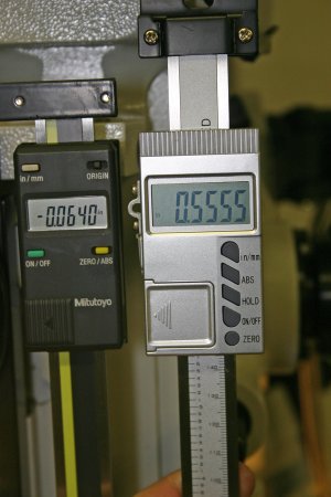
The quill style really is a no brainer for mounting & still maintaining access to existing mechanical functions. The grey one is the typical Chinese model, has larger display than Mitutoyo.
 

Attachments

  • IMG_8091_edited-1.jpg
    IMG_8091_edited-1.jpg
    68.8 KB · Views: 9
@TorontoBuilder Thank you for that little gem, you've kicked my creative juices into gear! :D

I've been going over in the back of my mind how I wanted to do the quill scale and like you, thinking that even though I have a mounted mag scale assembly it's too bulky. Since I have some tape left over from my Myford installation I've been thinking I'd roll my own with it. Your solution is almost perfect - for me and my machine that is.

My First has a nice flat machined surface on the right side, opposite the graduated scale so I think that's the ideal place for my mag scale tape and I have the added benefit that I get to keep my analog scale - just because.

I think I'm going to have a go at fixing the read head mount (similar to yours but on the other side) using either a split wedge type of keeper or maybe something else I can brew up that would keep me from having to dismantle the scale stop to tap it (the large bore) or something similar. A little more thought required in the morning on that.

If that doesn't work out then I have a model for a replacement stop knob with integrated read head mount.

D :cool:
 
Do you have a 4-axis DRO display box to capture the reading or what is the plan there?
The quill style really is a no brainer for mounting & still maintaining access to existing mechanical functions. The grey one is the typical Chinese model, has larger display than Mitutoyo.

We have a 4 axis DRO. It cost more but it was worth it IMO.

@Tecnico I was debating making a new longer ruler to replace the existing one just to retain the normal operation as well and use it in conjunction with the push button quill stop. So pretty much I'll be taking the screw apart anyways. But if I didn't want to go that route I could just drill and tap my two smaller holes by hand and be done
 
Last edited:
We have a 4 axis DRO. It cost more but it was worth it IMO.

I feel the same way. My 4 axis Ditron DRO will combine the quill and knee for one output and also display whichever one of them you choose alone. I have always found it difficult to move the quill a thou or two. But it's rinky dink simple to lock the quill and raise the knee a thou!

@Tecnico I was debating making a new longer ruler to replace the existing one just to retain the normal operation as well and use it in conjunction with the push button quill stop. So pretty much I'll be taking the screw apart anyways. But if I didn't want to go that route I could just drill and tap my two smaller holes by hand and be done

How about this.... The mag tape needs a stainless cover anyway. How about a stainless cover that is either etched with a ruler and or has a very thin mylar ruler strip over it!

Then you have both the DRO and the ruler!

Damn, where were all you guys and all this discussion when I did mine!

I wanted both too. My solution at the time was to lift the DRO Scale away from the quill to provide room to change and see the manual setting. I like tape right on the scale surface WAAAAY BETTER!
 
I feel the same way. My 4 axis Ditron DRO will combine the quill and knee for one output and also display whichever one of them you choose alone. I have always found it difficult to move the quill a thou or two. But it's rinky dink simple to lock the quill and raise the knee a thou!


How about this.... The mag tape needs a stainless cover anyway. How about a stainless cover that is either etched with a ruler and or has a very thin mylar ruler strip over it!

Then you have both the DRO and the ruler!

Damn, where were all you guys and all this discussion when I did mine!

I wanted both too. My solution at the time was to lift the DRO Scale away from the quill to provide room to change and see the manual setting. I like tape right on the scale surface WAAAAY BETTER!
So I'll have to look up that feature on the Ditron, since that it the DRO brand I have.. the D80.

I have been thinking of many ways to accomplish this, from making a graduated scale on the mill, or just trying to find a SS ruler I can cut down. I doubt you can find a ruler with extra steel prior to the start of the ruler though.

I had been planning to just embed my scale and cover/surround it with Loctite pc 7222 ceramic filled epoxy putty. It is very wear resistant and totally seals the scale without interfering with the poles, and you can omit the upper stainless steel cover strip. I plan to use this epoxy for all my embedded scales.
 
So I'll have to look up that feature on the Ditron, since that it the DRO brand I have.. the D80.

Yes, mine is a D80. It is a VERY COOL FEATURE!

I am planning to get a D80 for my lathe too (I considered a touch DRO but I prefer both units to work and behave the same.) I know that the D80 can calculate the compound angle, but I'm hoping it can also determine the component of the compound displacement and then combine that with the table or cross slide measurements. But that would be dessert after a great meal.

I have been thinking of many ways to accomplish this, from making a graduated scale on the mill, or just trying to find a SS ruler I can cut down. I doubt you can find a ruler with extra steel prior to the start of the ruler though.

Yes, I forgot that most rulers measure zero from the end. That's an issue. Especially since it needs to be a particular thickness too. Prolly not possible to find one.

I think that means getting one etched.

I had been planning to just embed my scale and cover/surround it with Loctite pc 7222 ceramic filled epoxy putty. It is very wear resistant and totally seals the scale without interfering with the poles, and you can omit the upper stainless steel cover strip. I plan to use this epoxy for all my embedded scales.

If this works, it's awesome! (Perhaps with the exception of the quill scale discussed above.) On a lathe it would also solve the grease, oil, and dirt issue.

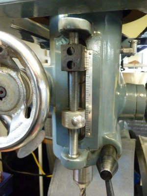
Here are close-up photos of my quill DRO Scale install. Because the quill Knob is round, only one screw is required to hold the sensor bracket in place. The scale does not interfere with reading the scale or adjusting the stop. As a bonus, the DRO can be used to adjust the stop with precision. I love it.

I am unsure of mounting the sensor itself such that it can read a magnetic strip without hiding a manual ruler scale behind it though.....

Also the flat face length where the ruler mounts is inadequate to accommodate the total length of the magnetic strip that is required. Not good...... Plus the feed clutch is in there too. More not good.

20230417_183402.jpg

20230417_183513.jpg


20230417_183703.jpg


In case you are wondering, the unused threaded hole in the sensor bracket is there to accommodate a post to provide cable relief.
 
Back
Top