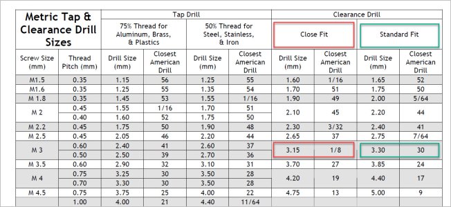
I just discovered something about many of the thread hole charts when it comes to their 'metrification'. Little Machine Shop for example. Not picking on them because others appear to do the same. I was wondering why my CAD drawings rarely aligned to the LMS wall chart in my shop. In my CAD program I select the hole from a drop-down which also specifies the standard. I can convert dimensions between imperial & metric & assumed that was the root of the issue.
For example a clearance hole for M3 fastener, all 3 common metric standards (ANSI, ISO & DIN) provide 3 categories: Close, Normal & Loose. All 3 have the same dimensions which correspond to mm drills in 10ths as shown in the spreadsheet. The LMS chart has only 2 categories, Close & Standard, neither of which correspond to the metric standards. And the substitute drills are kind of somewhere in between. This might not make any difference to your day to day work, but just be aware. I think its meant to be helpful to N-Am/Imp tooled shops to get something close.
For example a clearance hole for M3 fastener, all 3 common metric standards (ANSI, ISO & DIN) provide 3 categories: Close, Normal & Loose. All 3 have the same dimensions which correspond to mm drills in 10ths as shown in the spreadsheet. The LMS chart has only 2 categories, Close & Standard, neither of which correspond to the metric standards. And the substitute drills are kind of somewhere in between. This might not make any difference to your day to day work, but just be aware. I think its meant to be helpful to N-Am/Imp tooled shops to get something close.
Attachments
Last edited:


