• Scam Alert. Members are reminded to NOT send money to buy anything. Don't buy things remote and have it shipped - go get it yourself, pay in person, and take your equipment with you. Scammers have burned people on this forum. Urgency, secrecy, excuses, selling for friend, newish members, FUD, are RED FLAGS. A video conference call is not adequate assurance. Face to face interactions are required. Please report suspicions to the forum admins. Stay Safe - anyone can get scammed.

Tool Lathe indicator holder

Tool

Arbutus

Ultra Member
Premium Member
Well that was another Tuit well spent.

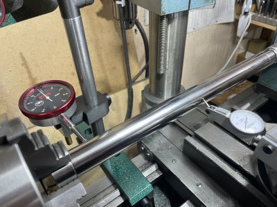
While working on the Eureka relief tool, I was having all kinds of problems with the DTI mounted in one of those wobbly magnetic indicator stands, teetering on the edge of the ways. The solution was this rear mounted indicator stand, which is sturdy and rigid by comparison.

The base clamps across the way, and as you can see it is relieved to match the cross section. Before cutting metal, I measured the ways, sketched the profile and printed a 1mm thick pattern to test the fit.

The DTI mount allows tilt, swivel and height adjustment. The indicator mounts horizontally face up which is really awkward to see, so I made a swivel and mounted a small stainless steel mirror. Works like a charm.

IMG_5554.JPG
IMG_5555.JPG


IMG_5556.JPG
Indicator support.jpg
 
Wow!!! Some Mighty Fine Work and Ideas there.

I think indicator holders and setups like this should be a focus for the entire membership. You can't machine what you can't measure! And you can't measure what you can't see!

I can't get to my shop today for photos without getting killed by SWMBO. We have 3 grandkids here and they need watching like a hawk!

@Dabbler and I had a long chat about such things when he was in Ontario for the Eclipse. He shared some ideas with me that I'd never thought of.

One of them was to add a large 1/4" plate of steel here:

20250216_091143.jpg

The thing is that cast iron is a poor place to put a magnet. But a magnetic indicator post will mount onto a steel plate with strength to spare. The plate needs to be fairly thick so the magnet is effective. 1/4" plate works just fine. Sheet metal doesn't.

I love your gimbals. Did you make those? Do you have drawings for B and C to share? I'm in the middle of a project I've been doing for several months now and I could sure use some gimbals like that! Where did you get the mirror?

20250216_091044.jpg

Did you consider a lip at A? A lip would trap the plate at the V way so nothing could come loose or fall. A tightening screw would not be needed.

I'd also add a clearance slot for the back v-way so the fixture could be used on the front v-way too and also further away from the headstock too.

I don't really like plunge indicators for that job. They put too much force onto the part and the stand and... then they lie! So I prefer dial test (needle) indicators for that job. They are generally not that good unless the needle is parallel to the work, but that's usually quite easy to arrange. As a bonus, they can often be positioned so that movement is easy to see. It's surprising how many machinists don't know that the needle on the better indicators usually has a clutch in it such that the needle can be rotated to a better position for easy viewing of the indicator face.

Lastly (for now anyway), I have some General and some Erick indicator holders like this.

Screenshot_20250216_094818_Amazon Shopping.jpg


They can be attached to the front, side, or back of a tool post to mount a dial test indicator that can be swung into or off of the work as needed. Very fast and easy to use. Perfect for dialing in a part on a four jaw, or measuring runout - especially axial runout where you have to take measurements along the length of the work.

Again, I think fixturing and metrology is something we don't share enough with each other. So a big thank you for doing that! And awesome work too!
 
Nice job, that looks very handy. Would love to make something like that for my Myford, it's always a bit tight to get an indicator in the places I need to, but It's always hard to find the time to make stuff like this. Mag base with a noga arm gets in most places, but not all.
 
What a great device. The expertise on this forum is amazing. More details would be great.
 
Here is a few photos of how I use the Erick and Generals to do that. These photos are using one of my generals that allow me to span the tool and attach directly to the tool holder above and below the tool. There are a million other ways to do it.

This photo shows the general and indicator setup to measure front to back wiggle. Typically the pin would be a bar so you can eliminate run-out along its length for axial runout. But this was just a photo op.

20250216_152452.jpg

20250216_162618.jpg

Here is the same thing using a vertical setup.

20250216_152230.jpg

20250216_163231.jpg

In both cases, the needle shaft is tangent to the front or top of the pin as appropriate.
 
I wasn't expecting this much interest!

The base is made from 1-1/2x1x12" CRS (PDF attached) it only fits the rear way on the V10P. The front clamping screw doesn't need to be gronked down since the profile is a close fit to the way cross section. A lip would make it hard to remove in this design.

The small parts are made from PETG-CF which has proven to be almost indestructible. The screw threads are tapped into the plastic, and all the joints in the swivel are lightly tightened to allow easy adjustment. Smaller screws down to M3 hold well when tapped into this plastic.

Swivel mount detail.png
Screenshot 2025-02-16 at 1.00.11 PM.png


The clamp levers are fitted to the socket head screw to take advantage of the light knurling on the screw head. The hole diameter is about 5 thou smaller and the screw is pressed in. With the correct interference fit, they are very durable. I use these in various sizes on most of my gadgets. Don't forget the top edge radius.
Screenshot 2025-02-16 at 2.05.05 PM.png


The mirror is made from 2mm stainless steel. They are sold as camping mirrors - about 4-1/4 x 3-1/2" about $5 from Amazoom.

The lever style indicator could also be mounted on a horizontal arm, but that would cost another Tuit.

:)
 

Attachments

Great work Arbutus. I think there are several people on here working on projects that your knuckle design will fit nicely.

What printer, slicer are you using? Hints settings on printing with petg-cf?
 
Great work Arbutus. I think there are several people on here working on projects that your knuckle design will fit nicely.

What printer, slicer are you using? Hints settings on printing with petg-cf?
lets see.... The printer I used there was the Bambu P1S and the filament is a generic PETG-CF from Elegoo. It prints perfectly using the "Generic PETG-CF" profile. The only trick really is to slow the printer down to 60mm/s and make certain the bed is clean or freshly prepared with BedWeld or similar. PETG does print with a non-heated chamber, although I do use a chamber heater in the Bambu set at 50C (another thread, another time).

I would never choose PLA or its derivatives for tooling because it a) warps; b) delaminates over time; c) machine oils destroy the plastic at a molecular level; d) exposure to sunlight (UV) damages the surface and it becomes chalky after a while.

ABS and ASA are also a good choice, but a heated chamber is usually needed for larger parts. Nylon910 is another option for foodsafe equipment.

First class design and fabrication, any plans on making a kit? Just the 3DP stuff. I would buy.
Thank you for the kind words! The knuckle joint is quite simple to print, and I made some from 6061 a while ago for a job but those took a day to make IIRC. 3DP is the way to go and with some fiddling the parts can be scaled slightly to say 25mm dia. If you are seriously interested in some parts, please send me a DM.

The lever style indicator could also be mounted on a horizontal arm, but that would cost another Tuit.
Mounting the lever indicator is actually much easier than I thought. The steel part that the DTI mounts onto just needs one hole drilled to accept the little dovetail pin and a locking screw to hold it. Thats the job for today.

The knuckles can be flipped left-right as well, so they are quite universal:
IMG_5579.JPG
IMG_5571.JPG

The test bar is a 1" chromed hydraulic piston rod. After reseating the chuck on the backplate I was able to get a TIR at the jaw face of 3 tenths.
And with some tiny adjustments at the tailstock, the test bar readings were within the noise window of the Kurt lever indicator, or 3 tenths over the full 16 inches. (Normally I would align the bar between centres, not held in a chuck.)
IMG_5570.JPG


These may also be of interest:
IMG_5576.JPG
Screenshot 2025-02-17 at 12.13.48 PM.png
Screenshot 2025-02-17 at 12.18.49 PM.png

Made from PETG, these ball-heads are useful for positioning and holding small items. The front surface mirrors (thanks Ian Moss!) are used in my macro photography projects. The socket is not simply split, there is a 2deg angled surface to allow the two socket shells to grip the ball when screwed together. Ball diameter is 20mm. The channel base is designed to fit over 2020 extrusion.

:)
 

Attachments

  • IMG_5572.JPG
    IMG_5572.JPG
    1.8 MB · Views: 4
Last edited:
Back
Top