• Scam Alert. Members are reminded to NOT send money to buy anything. Don't buy things remote and have it shipped - go get it yourself, pay in person, and take your equipment with you. Scammers have burned people on this forum. Urgency, secrecy, excuses, selling for friend, newish members, FUD, are RED FLAGS. A video conference call is not adequate assurance. Face to face interactions are required. Please report suspicions to the forum admins. Stay Safe - anyone can get scammed.

I bought the cheapest Y axis power feed I could find for my milling machine.

John Conroy

member
Premium Member
I paid $160 tax in from Vevor Canada.

https://vevor.ca/products/power-fee...ling-machine-110v?_pos=1&_sid=4b4240a60&_ss=r

The kit was very complete and installed with no issues. It seems to work fine so far. Less than half the price I paid for the Z axis one I bought last year.

20210116_105202.jpg
20210116_105423.jpg
20210116_121615.jpg
 
I mounted the travel stop switch to the same bracket as the Y axis DRO scale. The tracks are mounted with four M5 screws, holes drilled and tapped in the knee. Nothing about this in the instructions but if you have done one of these before the hardware is good.


The instruction manual is skimpy to say the least.

 
Too bad they don’t seem to carry drives for RF30 style mills.
 
it might be a fun project to adapt a cheap bridgeport style one to fit. you would have to fabricate a bearing/support block and shaft extension but I think it's doable.
 
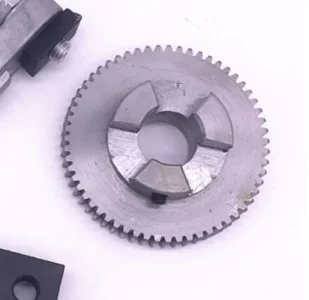
So this gear/dog combo engages the small drive gear in the unit.
Screen Shot 2021-01-17 at 2.13.09 PM.webp
If I'm not mistaken, on the version that John has, the small drive gear engages a bevel gear on the shaft of the mill.
I'm very confident that the guts of the two units are identical.
I think it would be pretty simple to make the pictured gear/dog and the associated brackets.
@John Conroy did you take any photos of the drive end of the unit before it went on?
 
OK, you would need a bracket/support/bearing block to bolt to the table on the mill and support the drive with the center hole aligned with the x axis lead screw. like the black piece in this pic.


The small pinion in this pic drives the bronze bevel gear supplied in the kit.


the support bearing in the drive unit runs on this sleeve to keep it centered on the shaft


The shaft needs to be extended so you can still have a hand wheel. Shaft extension show here.


The bronze gear drives the shaft through a key.


Shims are used to control the backlash between the 2 gears.


The key in the extension shaft engages the handcrank.


I don't know what the end of the lead screw looks like on an RF mill. Maybe it would be too difficult to extend the shaft through the drive. If it can be extended you would need to make 3 main parts. The adapter block to attach the drive to the mill table. The shaft extension and the sleeve that fits into the drive unit bearing and slides over the shaft.
 
Judging by these 2 pics there are no threads on the ends of the lead screw to easily attach a shaft extension but the shaft could be removed and threads added in a lathe.

rf30 shaft left end.webp
rf30 shaft right end.webp
 
I strikes me that if a block were added to the right end of the table, it could be made to work.
Pondering...
 
I’m curious about the left side handle on yours Craig.
How much past the end of the table does the lead screw project?

Both ends of the screw measure 17mm in dia.

The left side projects 60mm out from the mounting bracket and the bracket is 15mm thick.

The right side projects 80mm out from the mounting bracket and the bracket again is 15mm thick.

If that makes any sense...….
 
Back
Top