• Scam Alert. Members are reminded to NOT send money to buy anything. Don't buy things remote and have it shipped - go get it yourself, pay in person, and take your equipment with you. Scammers have burned people on this forum. Urgency, secrecy, excuses, selling for friend, newish members, FUD, are RED FLAGS. A video conference call is not adequate assurance. Face to face interactions are required. Please report suspicions to the forum admins. Stay Safe - anyone can get scammed.

How to finish a lathe gib holder

Tom Kitta

Ultra Member
IMG_20230522_141018[1].jpg


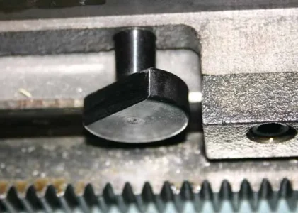
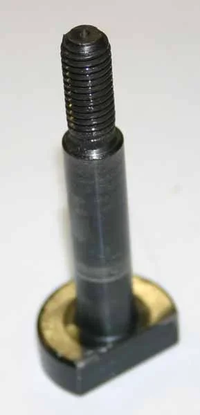
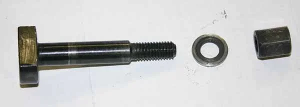
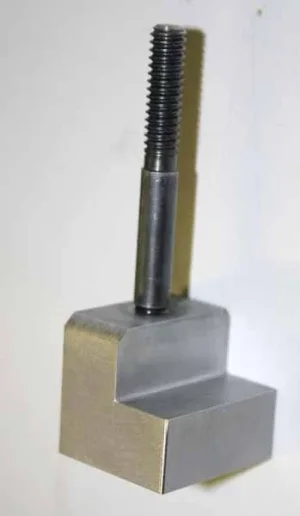
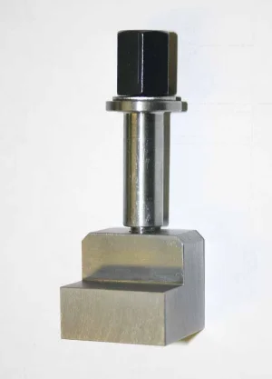
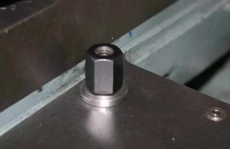
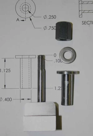
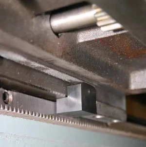
Here it is assembled in. But it does not tighten as I either have to add something to the "Green" area or I have to mill down a bit the area opposite to green.

So what should I do? Currently I think of adding a brass shim about 1mm thick to the green area.

What should I do? Other than this it fits perfectly. Original part was missing.
 

Attachments

  • IMG_20230522_141223[1].jpg
    IMG_20230522_141223[1].jpg
    259.6 KB · Views: 25
If that's also the carriage lock then it seems to me that it should be loose till tightened?
 
Mill the other side of what? I'm not following.
Tom can either make the part that bears against the bottom of the ways thicker with a shim or mill away some of the area that bears against the bottom of the carriage so that it doesn't bottom out before it clamps down on the underside of the way.
 
I wasn't quite sure if your issue was the same as mine, disregard if not. My 14x40 had a very vague feeling saddle lock. Very little contact area & it was acting at a distance from the saddle underside. It would spin on its axle, loose orientation or stick the saddle movement depending on the gravity of the moon. Just plain goofy.
 

Attachments

  • 2017-03-25_15-52-43.webp
    2017-03-25_15-52-43.webp
    5.2 KB · Views: 4
  • IMG_5875_edited-1.webp
    IMG_5875_edited-1.webp
    36.1 KB · Views: 5
  • IMG_5887_edited-1.webp
    IMG_5887_edited-1.webp
    7.6 KB · Views: 5
  • IMG_5884_edited-1.webp
    IMG_5884_edited-1.webp
    7.2 KB · Views: 5
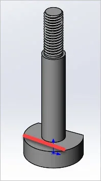
I made this one. A profiled foot
 

Attachments

  • IMG_5971_edited-1.webp
    IMG_5971_edited-1.webp
    7.7 KB · Views: 6
  • IMG_5969_edited-1.webp
    IMG_5969_edited-1.webp
    13.3 KB · Views: 6
  • IMG_5967_edited-1.webp
    IMG_5967_edited-1.webp
    12.7 KB · Views: 6
  • IMG_5963_edited-1.webp
    IMG_5963_edited-1.webp
    18.8 KB · Views: 5
  • IMG_5980_edited-1.webp
    IMG_5980_edited-1.webp
    32.1 KB · Views: 5
  • SNAG-3-26-2017 0000.webp
    SNAG-3-26-2017 0000.webp
    7.5 KB · Views: 5
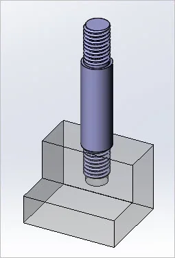
On my three lathes, the carriage lock block looks something like this:

E1E6E4FC-2B96-4DF3-9E10-FFAFE1CFD197.jpeg


For best clamping force, one needs a pivot so the block can clamp onto the underside of the way. This is a very powerful set-up - I usually only “snug” the lock bolt.
 
My Lathe is similar to @RobinHood but sideways.

Looking at it from the tailstock it looks like this:

20230524_202539.jpg


My drawing isn't great, the left side is quite a bit wider than as drawn. And the entire block extends along the way about 3 or 4 inches.
 
I wasn't quite sure if your issue was the same as mine, disregard if not. My 14x40 had a very vague feeling saddle lock. Very little contact area & it was acting at a distance from the saddle underside. It would spin on its axle, loose orientation or stick the saddle movement depending on the gravity of the moon. Just plain goofy.

My lathe is Czech made so they had enough foresight to add a pin - seen on picture that keeps things properly oriented.

There appears to be almost no difference height wise - maybe 0.001 between moving parts - this 0.001 could simply be wear.
 
Back
Top