I will get straight to the point. How do you/they handle (adjust) for the lateral forces created when using helical cut gears?
The rest of the story.
I have a gear box that has an input shaft from an electrical motor. The gear box reduces the speed of the motor. The input shaft is on two deep groove ball bearings and has a helical cut gear.
An idler gear is also helical cut to mesh with the input shaft gear and is mounted to a shaft that also is on two deep groove ball bearings.
The third gear is helical cut to mesh with the idler gear and it is the output shaft of the gear box. Supported by two deep groove ball bearings.
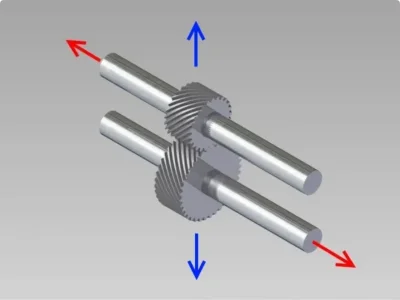
So far straight forward. When you power up the motor it will cause lateral movement in the input shaft causing it to move to the right due to the helical cut gear.
The idler will move to the left and the final drive will move to the right.
Now I throw a twist into the gear box. The output shaft can back drive the gearbox and drive the motor as a generator. When back driving the system the helical cut gears will move in the opposite directions. The final drive moves to the left, the idler to the right and the input to the left.
Under constant load the gears are in their happy state. When switching directions, the lateral forces in each of the shafts change direction and take up any free play. (usually with a clunk added).
Will shimming the lateral free play effect (or is it affect?) the mesh of the gears? I know in straight cut gears the proper mesh of the gear is important. Usually moving the gears in and out (radial) from each other in a parallel motion. With a helical cut gear I'm sure there is an ideal mesh in and out (radial) from each other, but something makes me think that the lateral play will also come into the picture.
On a side note. From the SKF bearing site, a deep groove ball bearing can handle radial and lateral loads.
Edit.... added an image to give a visual to the loads. Blue radial. Red lateral.

Last edited:


