• Scam Alert. Members are reminded to NOT send money to buy anything. Don't buy things remote and have it shipped - go get it yourself, pay in person, and take your equipment with you. Scammers have burned people on this forum. Urgency, secrecy, excuses, selling for friend, newish members, FUD, are RED FLAGS. A video conference call is not adequate assurance. Face to face interactions are required. Please report suspicions to the forum admins. Stay Safe - anyone can get scammed.

Half-Nut Engagement

thestelster

Ultra Member
Premium Member
I always strive to improve on my techniques, either doing better or getting faster, or both if possible.

Here is the scenario.

When cutting a thread with the lathe, we have to engage our half-nuts so the carriage locks onto the lead screw and away we go until we disengage the half-nuts.

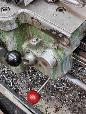
Depending on the thread pitch we want to cut determines at which mark on the thread chasing dial we have to engage. (See 2nd picture).

Now supposing we're going to cut a 16tpi thread. According to my lathe, I can engage the half-nuts at any line on the dial, and infact I can even engage between marks.

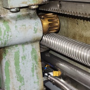
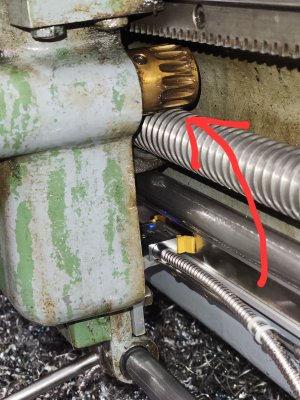
Now, this is an old lathe and the steel lead screw has some wear, and so does the bronze worm gear of the half-nut mechanism which meshes with the lead screw.

When cutting our 16tpi thread, would we get the most accurate thread profile and pitch if we always engaged on the same line? Or if we use the other marks as well, to average out the minor discrepancies from the wear of the lead screw and worm gear?

I know it really doesn't matter in practice, but in theory?
 

Attachments

  • 20240112_171756.jpg
    20240112_171756.jpg
    704.3 KB · Views: 14
  • 20240112_171815.jpg
    20240112_171815.jpg
    216.5 KB · Views: 14
  • 20240112_171840.jpg
    20240112_171840.jpg
    581.5 KB · Views: 14
When cutting our 16tpi thread, would we get the most accurate thread profile and pitch if we always engaged on the same line? Or if we use the other marks as well, to average out the minor discrepancies from the wear of the lead screw and worm gear?

I know it really doesn't matter in practice, but in theory?
Good question. I don't know the answer off hand. But I've often wondered that very same thing.

Because I don't know the theory on this one, I've always used the same mark no matter what thread it is. I know that will be the safe path when I'm cutting a thread that matters. But I confess that waiting for the dial to come around can seem like an eternity when I'm running at slow speeds and I usually am. So it would be good if I could develop some confidence in the method.

I only use the other marks when the thread I am cutting isn't all that important.

Now that I know I'm not the only one wondering about this, it would be interesting to do some more research and perhaps some experiments. Please post back here if you learn more.
 
Right or wrong I tend to pick a number to start on and stick with it for that thread that day. I also turn the lathe off whilst I rewind and set up for the next thread and I crank the apron till the number lines up then re-engage the half nuts and turn on the lathe.
 
I don’t think it would make any difference. The gear would have to be worn to the extent that you could close on the next set of threads. For an 8 tpi that would require an error of ⅛”. In any case with an 8 tpi lead screw if you’re cutting an 8, 16, 24 tpi etc you can close at any point, effectively ignoring the thread dial completely.
 
Yes, that what it is.

We make 2 threaded sections. 1 section we use the same line on the thread chasing dial, the second one is closing the half-nuts on all different lines. And then we measure the pitch and compare.
 
We make 2 threaded sections. 1 section we use the same line on the thread chasing dial, the second one is closing the half-nuts on all different lines. And then we measure the pitch and compare.

I like that. Building a bit on your idea, how about just using one section and only use one very fine surface cut with a very fine very sharp tool. Like a scribe on dykem. In fact, we could even mount a spring loaded scribe and use dykem! Then try each thread dial mark in succession and see how well they all line up. The magnifier comparator would still be an asset.
 
In any case with an 8 tpi lead screw if you’re cutting an 8, 16, 24 tpi etc you can close at any point, effectively ignoring the thread dial completely.

That's the part Stel would like to test. Just how reliable are the other marks?
 
The threading dial has zero effect on the thread accuracy. It’s sole purpose is to help us synchronize the spindle to the lead screw.

Thread accuracy only depends on the section of the lead screw you are presently using. E.G., if you cut a 1” long thread, your half nuts will engage in the same 1” long section of the lead screw at some distance away from the gear box, regardless of what number your thread dial shows when you engage.

If you now were to cut the same 1” thread at say 1 foot further away from the original position, then you’d use another 1” section on the lead screw also 1 foot further away from the first location. Again, thread dial numbers / lines have no effect.

The difference in thread accuracy of the above two cases is only a function of the wear difference between the two sections of lead screw used.

For most lathes, the lead screw has more wear towards the head stock - that’s where most threading is done. There is usually little to no wear at the TS end.

That is why on some Standard Modern lathes (SM1340, for example) the lead screw is reversible. Just take it out, turn it around and now you have a “brand new“ lead screw - well, at least an unused section - good for another 50 years.
 
The reason some thread pitches let you use all locations, some locations or just one is simple.

As mentioned by @RobinHood syncing the rotation and feed to engage at the same location every time. This is why some don't even disengage the threading level until the thread is completed.

Basically depending on the pitch these two different rotations and alignment points have only certain time they match and that location is determine by the harmonics of your lathe setup (initial design). Old school was one location ( because it takes lots of math to calculate those ratios) modern lathes someone has done the work for you. I was taught one location bit my lathe manual says depends.

Now to really mess you up, ELS and CNC really don't care because they are sync and turn on when needed, you just engage and the onboard computer does the rest.
 
I slept on this last night and concluded that I agree with @RobinHood. It doesn't matter.

To begin with, I don't look at the lead screw (or any screw for that matter) as having more than one section at any point along its length. That section has a profile to it. The half nut allows us to grab a particular set of lands of the lead screw at whatever point along the length of the lead screw we happen to be at. We can only grab a whole set of threads - no half threads allowed. That set of threads doesn't really travel. They just rotate. The half nut is what travels as it follows the thread geometry.

In other words, nothing about which point on the thread dial is chosen changes the way the half nut follows the lead screws. The screw doesn't move. The nut will follow the same path arriving at the same sequence of sections regardless of which rotation or point in a rotation is chosen.

End of story.

It is exactly the same no matter what tpi is chosen. Tpi only changes the ratio of how many turns the lead screw makes vs the spindle. It does not change how the half nut follows the lead screw.

Put another way, the half nut follows the exact same set of lead shaft profiles no matter what point is chosen. Only the index to the spindle changes. By selecting a different point on the thread dial, all you change is the index. The half nut will still follow the lead screw exactly the same.

@RobinHood's description of lead screw wear fits perfectly with this analysis.

All this said, there is a possibility that the threading gears are cut or worn unevenly. Since the thread dial essentially chooses the gear synchronization points, there is an opportunity for some sort of gear driven phase shift to occur. Which might in turn affect the target thread placement in some way.

The obvious one being those times when the half nut and thread dial do not coincide with the correct position of the spindle for that thread pitch and end up cutting a thread between threads.

The less obvious one is when a different set of teeth in the gear train line up with the spindle position but off set the leade screw by the phasing difference built into the gears. This is the only possible error that could result from choosing a different thread dial position to engage the half nut on.

The question that arises from this conclusion is: Does it matter? I don't think it does. If it exists at all, it only affects the spindle rotation ratio. Just taking a WAG at how bad it could be, it's impossible to imagine anything as bad as 1/2 a gear tooth. In a low count gear (say 20 teeth - low count being worst case IMO), that's a phase shift of just 9 degrees in the gear which translates to 1 degree of rotation on a 9 tpi thread. Less than a thou if my math is right. In other words even if the worst case is possible, which is itself unlikely, it's still insignificant.

I don't even see the point of doing any testing anymore.

What a great night's sleep I had. I feel better this morning than I have felt in a very long time!

That is why on some Standard Modern lathes (SM1340, for example) the lead screw is reversible. Just take it out, turn it around and now you have a “brand new“ lead screw - well, at least an unused section - good for another 50 years.

I did not know this. What a great feature. I will have to look at mine to see if it works that way too.
 
when a different set of teeth in the gear train line up with the spindle position but off set the leade screw by the phasing difference built into the gears. This is the only possible error that could result from choosing a different thread dial position
Yes!! This is exactly what I am referring to.

Since the chasing dial is connected to the worm gear, if in the past twenty years we always closed the half-nuts when the chasing dial is at the 1 mark, then that "slot" of the worm gear will be more worn than the "slots" of the other numbers.

No here is the issue. Lets say we're cutting a thread, we need 10 passes to get to full depth. Unbeknownst to us the #1 line slot of the worm gear is more worn than the rest. You're doing your passes of thread cutting closing the half-nuts at every mark other than #1. You're down to the last pass, you just measured your thread pitch with your thread micrometer, we need to make a final depth of cut of 0.001". We go to cut, but this time we close the half-nuts on the #1.

We measure and we overshot our pitch diameter becasue of that worn #1 slot because of as @Susquatch called it a phase difference.

Is this scenario plausible?
Unless I am mistaken, the worm wheel doesn't come into play when threading, just the half nuts. The worm and handwheel just follow the leadscrews "lead"..... The wear on the screw and nut should be the same no matter what line on the dial.....
 
Unless I am mistaken, the worm wheel doesn't come into play when threading, just the half nuts. The worm and handwheel just follow the leadscrews "lead"..... The wear on the screw and nut should be the same no matter what line on the dial.....
This is the interface I'm referring to. I'm calling the bronze part the worm (maybe I should be calling it something else?) And it's directly fixed to the thread chasing dial.

Maybe I'm not seeing how these parts work. I'll take a closer look. Maybe I just wasted everyone's time.
 

Attachments

  • 20240112_171840.jpg
    20240112_171840.jpg
    516.7 KB · Views: 3
This is the interface I'm referring to. I'm calling the bronze part the worm (maybe I should be calling it something else?) And it's directly fixed to the thread chasing dial.

Maybe I'm not seeing how these parts work. I'll take a closer look. Maybe I just wasted everyone's time.
My bad, I was thinking of the worm on the handwheel. On my South Bend, the lines don't quite line up when I engage the half nuts, but trail just a little bit behind. It hasn't bothered me enough to try and change it, as I haven't had any threads go south because of that. Now, the nut at the handwheel has screwed a few things up from time to time.......:rolleyes:
 
Yup, I wasted everyones time. My sincerest apologies. I thought, incorrectly, that the bottom steel half-nut meshed with the bronze worm gear. When in fact, behind the worm gear is the upper portion of the half-nut, d'oh!! The bronze piece is just there for the ride.
 
Yup, I wasted everyones time. My sincerest apologies. I thought, incorrectly, that the bottom steel half-nut meshed with the bronze worm gear. When in fact, behind the worm gear is the upper portion of the half-nut, d'oh!! The bronze piece is just there for the ride.

Not only that, but all those parts in the carriage assembly follow the same screws. Any wear there will not translate into a phase shift that can impact or be impacted by the thread dial location. All the screws merely rotate so the only influence is wear that relates to the carriage position not the carriage gear engagements.

The gears I highlighted that could cause a phase shift are all inside the headstock (or the back of the headstock). However, my math says that even the most severe result is under a thou and more likely under microns.

Only the wear in the leadscrew affects anything meaningfully and that wear is a constant for any given threading job for normal threading lengths. Now if you are cutting a long precise lead screw, it's time to worry about it.
 
Back
Top