• Scam Alert. Members are reminded to NOT send money to buy anything. Don't buy things remote and have it shipped - go get it yourself, pay in person, and take your equipment with you. Scammers have burned people on this forum. Urgency, secrecy, excuses, selling for friend, newish members, FUD, are RED FLAGS. A video conference call is not adequate assurance. Face to face interactions are required. Please report suspicions to the forum admins. Stay Safe - anyone can get scammed.

Tips/Techniques Finding out 3ph motor voltage without a nameplate?

Tips/Techniques

Dan Dubeau

Ultra Member
Long story short.....I have no idea what Voltage my Shaper runs at. This thing has been holding my floor down for about 13 years now, and It's time to get it moving under it's own power......

I bought it from a coworker in 2010 (he bought it in the mid 2000's), He bought it because it was cool, but hardly ever used it. I bought it because it was cool.......it was actually my first machine tool and it's sat in almost every corner of my shop during the many transformations lol. We haven't worked together in about 7-8 years now, but he thinks it was 575, whereas I seem to recall it being 240v 3 phase. Specifically due to the fact that I remember the story about him having to buy a step up transformer when he bought his mill later, because his phase converter was only 240v at the time, and I also kind of remember him wiring it up directly to his idler motor in his shop and running it for me when I bought it. Recalling that story to him, neither us us are sure anymore......

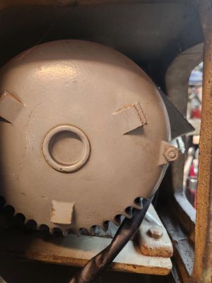
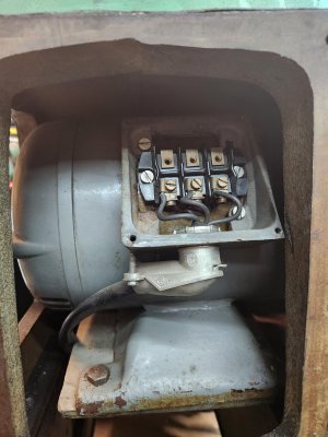
Anyway, there is no name plate on the motor or this would be a pretty pointless thread :D. It's buried in the casting, and somewhat tough to see all around. I've pulled off every cover and looked it all over as best I can with an inspection mirror where I can get one, but short of pulling the motor out to see if anything is written on it somewhere or on the bottom are there any simple tests with a multimeter, or other ways one can use to tell the winding voltage, or at least make an educated guess between 240 and 575. I know it's 3 phase.

JZgNMys.jpg

RO9BHrt.jpg

Kd1N29m.jpg
0SKE6VN.jpg
Rx9ASqG.jpg


UFwepzd.jpg
AZfBIv9.jpg


The only numbers on it, mean nothing to me, but maybe to someone? Under where the nameplate should be was stamped 1, then under it 2531177

Beside the junction box is stamped A, 203, A, and on the other side 7974.

Pretty sure they're useless manufacture markings, but ?
JzRQm4O.jpg


YF94u7T.jpg

hBYjaU0.jpg


I started off about 60% sure it's 240v but the 40% uncertainty is that this is a Canadian industrial machine, and being 240v 3ph would be pretty rare. A lot can happen to a machine over the years though (Like a nameplate falling off.), so there's no guarantees. But the paint on the motor is from the same time CB flipped it. I was hoping there'd be a note or piece of paper tucked inside one of the covers, but nothing. The wire to the motor doesn't have any discernable voltage rating on it (I didn't strip it back), but the wire coming out the switch is 600v rated. Again, no gurantee of anything, BUT the motor wiring does look a little small though, doesn't it, which leans me back towards the 575 side a lot.....
lHy7Dqw.jpg


Last question. How bad would it be to simply hook it up to a 240v vfd to try it? I'd guess it around 2hp or under just based on size. My vfd should be fine to handle the current draw, but theres always the unknown.....If it IS 240v, great, motor should hum as intended. If it's 575, what am I in for? Cooking the windings would be bad, but not the end of the world. Frying my VFD would be something I would not like to do........I "think" it would be fine to run for a short period of time and nothing bad would happen. Perhaps run hot, or not at rated specs (whatever they are), but nothing catastrophic. Probably much worse the other way running a 240v on 575. Would be nice to know though.....
 

Attachments

  • NIcbZRR.jpg
    NIcbZRR.jpg
    290.5 KB · Views: 7
  • js9nQAa.jpg
    js9nQAa.jpg
    393.8 KB · Views: 7
In the 7th picture it says if you want to renew the contacts, quote model No. 6-200-3.

For a full list of parts get publication No. 12350 from your nearest Cutler-Hammer district office.

I would go to my nearest search engine. ;)
 
All the motor starter stuff is pretty useless for figuring out what voltage it is, except the heaters. If they have a number on them, consult the chart. Might give you an indication. Based on the smallish motor leads, i'm guessing 575v
 
Could you take it to a motor repair shop they should know.
Ya, I could probably do that. Most likely the best most sure option. But how would THEY find out? I'm curious. I was hoping to avoid having to take it out, and that somebody had a neat trick to measure between windings and use some simple formula I'd never heard about......
 
All the motor starter stuff is pretty useless for figuring out what voltage it is, except the heaters. If they have a number on them, consult the chart. Might give you an indication. Based on the smallish motor leads, i'm guessing 575v
I'll check them out, and see what I can find. That wiring is kinda small though right? The more I think about that now, I'm really leaning towards 575v. And the fact that he never had it properly powered in the first place. Entirely possible and plausible......

I mean, if it's never had a tag on it, he could have simply just guessed and hooked it up to his converter which ran his lathe, and just assumed that because it ran, it was all good. I think the only thing he ever cut with it was a keyway or two, so probably less than a couple hours of use over a few years.
 
Hey Dan, I'm leaning Darren's way.

Why don't you give emotors a call. They MIGHT be able to help.

Failing that, I'd pull the motor so I could give it a good looking over for plates and other info. If that gave no joy, I'd take it to a motor shop and see if they could help.
 
If you plan on trying it on 240V with your VFD, make sure to disconnect all the belts. If the motor ends up requiring 575V, at least with no load and only 240V, you will not heat up the windings too quickly and it should not let the magic smoke out. The VFD should protect the motor in any case.

I particularly like @Darren ’s idea of comparing the installed heater numbers to the nice table given in the Cuttler-Hammer cover. If they are rated for very low amps, then there is a very high probability that the motor requires 575V.

OTOH, if your friend ran it off of his 240V RPC without blowing the heaters, then maybe the motor is wound for 240V… unless someone before him already changed out the heaters to run the motor on 240V…

There is a sure fire solution to this if the voltage can’t be confirmed: replace the motor with a 240V, 3PH one and run it off your VFD. Removes ALL the guess work.
 
We had a very recent discussion about this, but here are a few things:

The 600V rating on the wire indicates that the insulation is rated for use in circuits up to 600V. In Canada and the US, all modern commodity wire is rated for 600V. The limiting factor is the flammability of the insulation and not the arcing constant. This is a function of the UL / CUL test & certification method. Higher voltage systems typically use air as the insulator, or liquids like PCB

The gauge of the wire will indicate maximum current it can conduct. Building codes specify circuit breaker sizes for common gauges, but those limits are based on wires installed in walls and other inaccessible and flammable locations without shielding. Wires that are installed inside of fixtures or machines can carry substantially higher current at the same gauge. For example, the common 14-2 wire is limited to a 10A breaker by code, but it is common to see it carry 50A inside a fixture - the fuse current is actually around 160A. The reason why this is safe, is because of the grounded case enclosing the wire. And yes, UL has standards for how thick the ferrous metal has to be etc. Any of the 'old' machines have ample metal around these parts for other reasons - vibration, rigidity etc.

It is almost impossible to damage your VFD by connecting it to any motor. The worst situation would be if the motor has short circuits inside it. But the VFD supplies voltage at frequency, and limits current (depending on your model, it could do this via fuse / breaker or using digital circuit). Whichever model, if it has a UL / CUL or CSA or any other regulatory stamp on it, it has this protection. It must have it to prevent fire

3-phase AC motors can be run on a wide range of voltages as long as the voltage does not exceed the internal arc-insulation rating. So assuming that it was a 575V motor, then running on 208V is just fine. if the load of the motor is too great, it may fail due to a thermal insulation failure (that's where the classic burning smell comes in) and it won't develop the same power as it it were run with the higher voltage. And the speed, amperage and every other number on the name plate will change, but you don't have a name plate anyways, so its swag time anyways ;)

There are limits of course, but a short test run is unlikely to cause much harm
 
Quick math. 3 hp will be roughly 2500 watts. 2500 watts at 240 volt is 10 amps. Effective resistance of a 240 volt motor at 10 amps is 24 ohms.

2500 watts at 575 volt is 4.3 amp. Effective resistance of a 575 volt motor at 4.3 amp is 133 ohms.

So feeding 240 volt to a motor that has an effective resistance of 133 ohms will be a current draw of about 2 amps, works out to about 3/4 hp.

For an induction motor, the effective resistance is a function of ac frequency.

Running a 575 motor on 240 v will not destroy the motor or vfd, it will just result in a much lower output torque. RPM is frequency related, torque is current related. So if it is a 575 motor, at 240 it will be the same RPM, maybe output 1/2 or 3/4 hp, and will be significantly lower current draw than a real 240v 3hp motor.

This is not engineering math and way oversimplified.
 
We had a very recent discussion about this, but here are a few things:

The 600V rating on the wire indicates that the insulation is rated for use in circuits up to 600V. In Canada and the US, all modern commodity wire is rated for 600V. The limiting factor is the flammability of the insulation and not the arcing constant. This is a function of the UL / CUL test & certification method. Higher voltage systems typically use air as the insulator, or liquids like PCB

The gauge of the wire will indicate maximum current it can conduct. Building codes specify circuit breaker sizes for common gauges, but those limits are based on wires installed in walls and other inaccessible and flammable locations without shielding. Wires that are installed inside of fixtures or machines can carry substantially higher current at the same gauge. For example, the common 14-2 wire is limited to a 10A breaker by code, but it is common to see it carry 50A inside a fixture - the fuse current is actually around 160A. The reason why this is safe, is because of the grounded case enclosing the wire. And yes, UL has standards for how thick the ferrous metal has to be etc. Any of the 'old' machines have ample metal around these parts for other reasons - vibration, rigidity etc.

It is almost impossible to damage your VFD by connecting it to any motor. The worst situation would be if the motor has short circuits inside it. But the VFD supplies voltage at frequency, and limits current (depending on your model, it could do this via fuse / breaker or using digital circuit). Whichever model, if it has a UL / CUL or CSA or any other regulatory stamp on it, it has this protection. It must have it to prevent fire

3-phase AC motors can be run on a wide range of voltages as long as the voltage does not exceed the internal arc-insulation rating. So assuming that it was a 575V motor, then running on 208V is just fine. if the load of the motor is too great, it may fail due to a thermal insulation failure (that's where the classic burning smell comes in) and it won't develop the same power as it it were run with the higher voltage. And the speed, amperage and every other number on the name plate will change, but you don't have a name plate anyways, so its swag time anyways ;)

There are limits of course, but a short test run is unlikely to cause much harm

Thank you for the post, and explaining a bit more what to expect running on the wrong voltage.
 
Is there a control transformer (i.e. check what taps the the high voltage side of the control transformer are wired)? It is very unlikely that the coil on the contactor would be at line voltage. I find that most machines use 120V (or 24V) for the control voltage - certainly not 575V. If there is no control transformer, then the line voltage is not going to be 575.

Also, there should be labelling on the contactor coil (the actual little coil that pulls contactor) - you may have to disassemble the contactor to find it. See what it indicates.

Let us know. David
 
Quick math. 3 hp will be roughly 2500 watts. 2500 watts at 240 volt is 10 amps. Effective resistance of a 240 volt motor at 10 amps is 24 ohms.

2500 watts at 575 volt is 4.3 amp. Effective resistance of a 575 volt motor at 4.3 amp is 133 ohms.

So feeding 240 volt to a motor that has an effective resistance of 133 ohms will be a current draw of about 2 amps, works out to about 3/4 hp.

For an induction motor, the effective resistance is a function of ac frequency.

Running a 575 motor on 240 v will not destroy the motor or vfd, it will just result in a much lower output torque. RPM is frequency related, torque is current related. So if it is a 575 motor, at 240 it will be the same RPM, maybe output 1/2 or 3/4 hp, and will be significantly lower current draw than a real 240v 3hp motor.

This is not engineering math and way oversimplified.
Thanks. I figured there had to be some sort of simple mathematical way to guesstimate.
 
All the motor starter stuff is pretty useless for figuring out what voltage it is, except the heaters. If they have a number on them, consult the chart. Might give you an indication. Based on the smallish motor leads, i'm guessing 575v
If you plan on trying it on 240V with your VFD, make sure to disconnect all the belts. If the motor ends up requiring 575V, at least with no load and only 240V, you will not heat up the windings too quickly and it should not let the magic smoke out. The VFD should protect the motor in any case.

I particularly like @Darren ’s idea of comparing the installed heater numbers to the nice table given in the Cuttler-Hammer cover. If they are rated for very low amps, then there is a very high probability that the motor requires 575V.

OTOH, if your friend ran it off of his 240V RPC without blowing the heaters, then maybe the motor is wound for 240V… unless someone before him already changed out the heaters to run the motor on 240V…

There is a sure fire solution to this if the voltage can’t be confirmed: replace the motor with a 240V, 3PH one and run it off your VFD. Removes ALL the guess work.
c8yGuTz.jpg


Thanks for the tip to check the heater #. Pretty good bet this is a 575 motor I would think now eh? #1026

Guess I gotta finish my phase converter now :(

I have almost everything I need except for a few small things. Was all set to finish building it this summer until Rauce posted his Excello part out with a 230v motor and VFD. So I bought that to get my Mill running, and back burnered the phase converter project. I was REALLY hoping this would also be 230v so I could simply buy another VFD and get on with making chips.....
 
Is there a control transformer (i.e. check what taps the the high voltage side of the control transformer are wired)? It is very unlikely that the coil on the contactor would be at line voltage. I find that most machines use 120V (or 24V) for the control voltage - certainly not 575V. If there is no control transformer, then the line voltage is not going to be 575.

Also, there should be labelling on the contactor coil (the actual little coil that pulls contactor) - you may have to disassemble the contactor to find it. See what it indicates.

Let us know. David
I didn't see a transformer, but will admit to not contorting myself up to look up inside the casting any where else besides around the motor. I doubt there is though.

Good idea about looking at the coil directly.
 
What is your guess on the horse power? A rough rule of thumb is: 575V - 1 HP per amp. In 240V you need btw 3.5 to 4.5 amps per HP (depending on slip, fan size, the design voltage 208/220/230/240 etc).

Could be just those two (or 4) screws on the square cover over the coil. The control looks entirely local to that enclosure - perhaps that would allow them to use 575V for the coil, thus not needing to incorporate a control transformer? The control transformer still has to be inside some sort of an enclosure, it would not be casually bolted inside the casting. I have machines dating back to the 1950s, they still have all the electrical bits inside a dedicated box (very nicely done as part of the machine casting, not a separate sheet metal box - but it is still an enclosure).
 
Last edited:
Post a few pics of the whole machine Please....
Y737kSH.jpg
gAF36NT.jpg


It's a hideous paint job. Not original, but In my searching the net for info over the years, I have found 2 others painted the same way. Probably all came from the same shop or dealer with a bored Nephew on summer break.

The frame it sits on, while handy for moving it around all these years, will have to go, or get modified with fixed legs when I get it running. I just got a chuckle typing this out thinking back to the night I bought it, running it in the garage, and it was dancing around about to pull the cord out lol.
 
What is your guess on the horse power? A rough rule of thumb is: 575V - 1 HP per amp. In 240V you need btw 3.5 to 4.5 amps per HP (depending on slip, fan size, the design voltage 208/220/230/240 etc).
I'd guess it's about 1.5-2hp. Robinhood posted the lathes.co.uk site which states similar. I seem to recall reading the same elsewhere too back around when I bought it. It's not a big motor, and the shaft is 3/4 (I think).
 
Back
Top