With 8 3 phase motors in the shop, it was time to come up with a better way to run the motors other than with two VFDs (which were connected to the motor that I was about to use and then swapped to the next motor) --> welcome the RPC. I bought an used one from a colleague that was powering an air compressor, but had not been used for about 2 years. It was a very basic unit with no motor/circuit protection and was not operational when I got it. I repaired it, but knew it needed a "facelift".
Here it is as I bought it
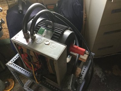
It gave me the basic components: idler motor, start capacitors, run capacitors, and differential voltage relay. I found an used motor contactor / overload protection and a much bigger cabinet; also, some switches and control lights. I did have an old contactor with a 575V coil - which was replaced with a 240V coil. I had a lot of #10 AWG wire, terminal ends, and a bunch of time...
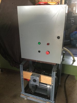
Here is what the new set-up looks like. The red light indicates that there is power to the unit, but it is not running
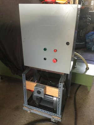
With the RPC running, the red light is out, the green light is on (plus one can hear the idler motor of course, although it is surprisingly quiet!)
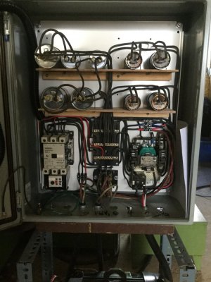
Here is the inside
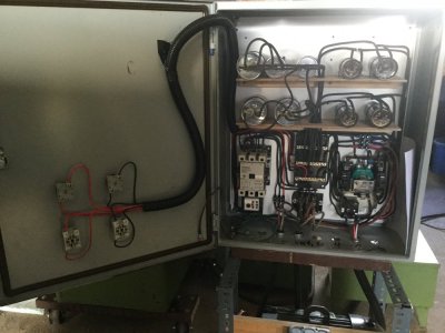
On the door we have the back ends of the switches and control lights. In the box, bottom left, is the main contactor / motor overload relay. Above it are the run caps. Top right are the start caps. Below them is the start contactor, with the differential voltage relay for control, just below it. In the lower centre are the bus bars. All feeds to/from the RPC are from the bottom.
Here is a closer view
This is the schematic I came up with - based on designs found on PracticalMachinist.com and other sources; (yes, I did use a trial version of a circuit drafting software...)
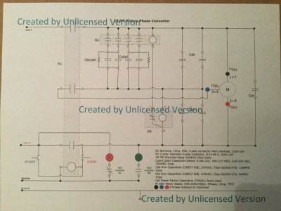
Some of the performance numbers while the RPC is running under no load:
VL1L2 = Vab: 246.1 VAC
Vac: 255.6 VAC
Vbc: 257.6 VAC
IL1L2 = Iab: 5.1 A
Iac: 15.3 A
Ibc: 12.9 A
Cab: 150 MFD
Cbc: 90 MFD
Cstart: 700 MFD
Cpf: not used
With a ~ 2.5hp motor load, Vac and Vbc drop closer to the line voltage (Vab) and the currents Iac and Ibc go up, but start to equalize. Line current increases to about 11.0 A.
How I built this unit is based on what I had on had / was able to source locally. By no means is it the only way to build a RPC.
In conclusion, the RPC project was successful and I am looking forward to run my machines with it...
Here it is as I bought it

It gave me the basic components: idler motor, start capacitors, run capacitors, and differential voltage relay. I found an used motor contactor / overload protection and a much bigger cabinet; also, some switches and control lights. I did have an old contactor with a 575V coil - which was replaced with a 240V coil. I had a lot of #10 AWG wire, terminal ends, and a bunch of time...
Here is what the new set-up looks like. The red light indicates that there is power to the unit, but it is not running

With the RPC running, the red light is out, the green light is on (plus one can hear the idler motor of course, although it is surprisingly quiet!)

Here is the inside

On the door we have the back ends of the switches and control lights. In the box, bottom left, is the main contactor / motor overload relay. Above it are the run caps. Top right are the start caps. Below them is the start contactor, with the differential voltage relay for control, just below it. In the lower centre are the bus bars. All feeds to/from the RPC are from the bottom.
Here is a closer view

This is the schematic I came up with - based on designs found on PracticalMachinist.com and other sources; (yes, I did use a trial version of a circuit drafting software...)

Some of the performance numbers while the RPC is running under no load:
VL1L2 = Vab: 246.1 VAC
Vac: 255.6 VAC
Vbc: 257.6 VAC
IL1L2 = Iab: 5.1 A
Iac: 15.3 A
Ibc: 12.9 A
Cab: 150 MFD
Cbc: 90 MFD
Cstart: 700 MFD
Cpf: not used
With a ~ 2.5hp motor load, Vac and Vbc drop closer to the line voltage (Vab) and the currents Iac and Ibc go up, but start to equalize. Line current increases to about 11.0 A.
How I built this unit is based on what I had on had / was able to source locally. By no means is it the only way to build a RPC.
In conclusion, the RPC project was successful and I am looking forward to run my machines with it...
Last edited:
