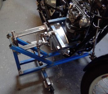
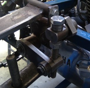
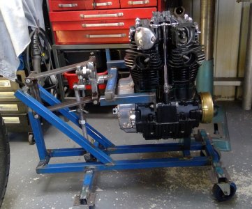
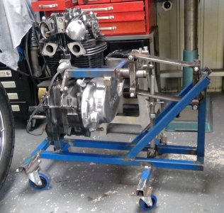
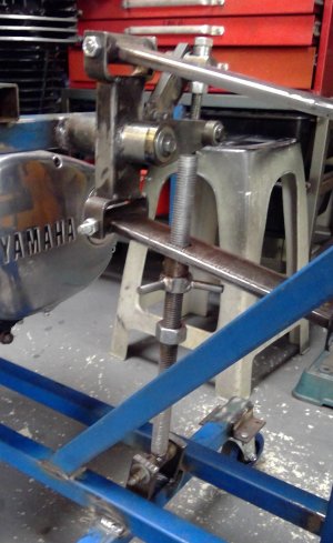
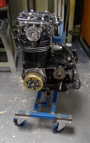
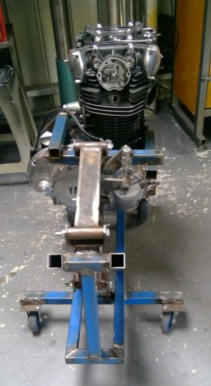
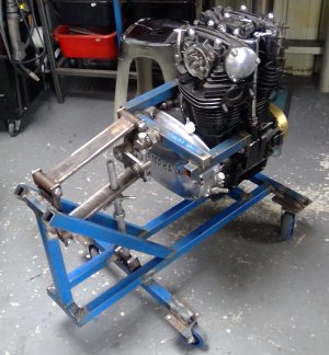
This is an engine removal, tilting lifting thingie I made for my XS650. The XS650 motor is a very tight fit in the frame, In their wisdom, the Japanese decided if you need to work on the engine, it should be removed from the frame. But removing the engine from the frame is not an easy job as there’s only mms to spare between frame and engine parts., so, a fair bit of wiggling, twisting, manoeuvring and lifting is required. It can be done by hand, but as the motor weighs somewhere around 180LB and there being very few places to grab the thing it isn’t easy. Commercially available engine cranes can be used, but due to the tight tolerances between engine and frame and the amount of manoeuvring required, getting the engine out without scratching and chipping the paintwork is virtually impossible without padding the frame with carpet or inner tubes. So, I made this thingie that tilts, lifts and rolls, and this is how it works:
First remove front, top and rear engine mounts and disconnect all the electrical connections. I also removed the carbs and starter motor. They probably didn't need to be removed, but just to be safe and give a better visual of the lower engine mount, I thought it wise.
Then attach the thingie to the engine via the front mount and the upper rear mount, take the strain and remove the long lower engine bolt and the lower rear bolt, tilt the motor forward a few degrees and lift the engine several mms then roll the thingie forward several mms. Tilt the motor forward again a few more degrees until the rear rocker mount sits under the highest point of the top frame tube mount and the lower frame mount sits between the starter motor mount and the lower engine mount, lift the engine again until the lower engine mount will clear the starter and engine mount, that leaves two or three mms clearance between engine and frame, top and bottom Then roll the thingie out the right hand side about 60mm so the rocker box mounts clear the top frame tube. Finally, lift the engine a few mms again until the sump studs underneath will clear the frame and wheel the engine away from the frame. Hey presto, engine out, no padding required for the frame, and no scratching the paintwork. It took around 10 minutes.
The engine can be left in the thingie for top end repairs, and alternator and clutch repairs if the motor is turned around in the thingie. After I’ve finished repairs on the top end, I intend on modifying the thingie so the engine can be rotated upside down, allowing the bottom end and gearbox to be disassembled.
Attachments
-
 1.jpg345.5 KB · Views: 19
 -
 3.jpg351.7 KB · Views: 20
 -
 4.jpg437.8 KB · Views: 19
 -
 WIN_20231014_16_00_29_Pro.jpg423 KB · Views: 19
 -
 WIN_20231014_16_00_42_Pro.jpg276 KB · Views: 16
 -
 WIN_20231014_16_01_53_Pro.jpg285.6 KB · Views: 14
 -
 WIN_20231014_16_02_39_Pro.jpg258.7 KB · Views: 13
 -
 WIN_20231014_16_02_53_Pro.jpg360.6 KB · Views: 19
