• Scam Alert. Members are reminded to NOT send money to buy anything. Don't buy things remote and have it shipped - go get it yourself, pay in person, and take your equipment with you. Scammers have burned people on this forum. Urgency, secrecy, excuses, selling for friend, newish members, FUD, are RED FLAGS. A video conference call is not adequate assurance. Face to face interactions are required. Please report suspicions to the forum admins. Stay Safe - anyone can get scammed.

Drilling precision holes without a mill?

SomeGuy

Hobbyist
For my RC build I am going to be making some sprocket mounts for fitting to a shaft. Here's what one of the sprockets look like:

aluminum-sprockets-16t-3.jpg


So I need to make a small mount with at least 4 bolt holes that will line up with the holes in the sprocket but I don't have a mill (yet). I do have a drill press though.

I was thinking I could just make a simple jig where I use one of the sprockets as a template to put a pin on a scrap steel plate for the center and drill 4 holes, tap them (so I can securely pin the parts in place), then use the template to locate the holes on the sprocket mount and ensure spacing while drilling on the drill press.

Needs to be fairly accurate as these will be spinning at upwards of ~2000rpm, material will be aluminum.

Any better ideas?
 
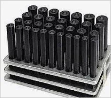
A slightly more direct way if you have lathe. Make a dedicated drill guide that has OD to snugly fit the sprocket hole ID. Guide also has a pilot hole from which to drill directly into your part. Ultimately you would open up these holes to whatever fits in there, dowel pins, threads for bolts. Or maybe depending on size required maybe you are home free right there. It might be beneficial to make 2 identical drill jigs (from same stock while in the lathe) so you have one to index & hold on hole#1 & the other guide to drill the reminders from hole to hole. This isn't much different than transfer punches, but those are only as concentric as the shank OD happens to fit & guessing the sprocket is rather thin.
 

Attachments

  • SNAG-1-27-2022 000.webp
    SNAG-1-27-2022 000.webp
    10.5 KB · Views: 1
  • SNAG-1-27-2022 001.webp
    SNAG-1-27-2022 001.webp
    2.6 KB · Views: 1
For my RC build I am going to be making some sprocket mounts for fitting to a shaft. Here's what one of the sprockets look like:

aluminum-sprockets-16t-3.jpg


So I need to make a small mount with at least 4 bolt holes that will line up with the holes in the sprocket but I don't have a mill (yet). I do have a drill press though.

I was thinking I could just make a simple jig where I use one of the sprockets as a template to put a pin on a scrap steel plate for the center and drill 4 holes, tap them (so I can securely pin the parts in place), then use the template to locate the holes on the sprocket mount and ensure spacing while drilling on the drill press.

Needs to be fairly accurate as these will be spinning at upwards of ~2000rpm, material will be aluminum.

Any better ideas?
Do you have a 3d printer?

If you did I'd print a jig that has a concentric boss that drops into the shaft hole and at least one detent that interlocks with a sprocket. Print the concentric hole array to use as a guide in the drill press at the nominal drill size. That will provide a tight fit for a drill and assure concentricity. I could print up such a part in 20 minutes or less.

I have also just laser printed markings on paper and then carefully glued that to the material being cut assuring it is as concentric as possible to the part. Then a center punch and just drilling

Never thought about using the 3d printer to make the jig, that's a great idea!

(I have an Creality Ender 5)
 
All of this is done with the lathe turned off

Blank in the lathe. DON'T DRILL THE BLANK
mark the blank against the chuck jaw so you can return it to the same point
Put a v-point tool bit in the tool post, with the bit 90* off from normal. Adjust the tool height so the point is on centre. Or put a scriber in the tool post, I use a tool bit because it's easier to hold. if you have a drill chuck that fits in your tool post, or a boring bar holder, use them with a scriber.
put the lathe in your lowest gear so the chuck won't rotate without effort, or block the chuck jaw so it can't move
use the bit to scribe a line across the face of the blank
rotate the chuck 90*-ish by hand and scribe again.
Do this a few times, so now you have a bunch of lines that will give you a very close centre measurement.
Put the bit in the normal way and align with the centre height
Move the tip of the bit to the centre point. the more accurate you get this, the more accurate the final hole placement
Move the bit out 0.385"
scribe a circle.
You now have a centre point, a radius, and some careful work with a square will get you all 4 points
check against your gear
fine punch, centre punch, drill press (use a vise clamped to the table) should get you well within a few thou.
Put the blank back in the lathe and bore as needed
 
Last edited:
Back
Top