• Scam Alert. Members are reminded to NOT send money to buy anything. Don't buy things remote and have it shipped - go get it yourself, pay in person, and take your equipment with you. Scammers have burned people on this forum. Urgency, secrecy, excuses, selling for friend, newish members, FUD, are RED FLAGS. A video conference call is not adequate assurance. Face to face interactions are required. Please report suspicions to the forum admins. Stay Safe - anyone can get scammed.

Draw bar rattle

Susquatch

Ultra Member
Administrator
Moderator
Premium Member
I've been annoyed at how the draw bar seems to rattle around on both my mills (Hartford & Bridgeport). It's fine at the business end where it screws into an R8 tool holder. However, the top of the draw fits too loosely into the top of the spindle.

Here is my fix. Super easy to do. Rattle is gone.

20211120_162609.jpg


The root of the problem is that the Drawbar is a 7/16 bar with 7/16-20 "ROLLED" threads on it. Because the threads are rolled, they are a bit bigger than the drawbar shaft. Therefore any regular bushing slipped over the threads ends up loose on the shaft.

The spindle ID is 0.512 on both mills. A custom fit nose goes into the spindle shaft and guarantees that the shaft is centered at the top of the spindle too.

The trick is to cut shallow threads so the thread ID on the collar is the same as the Drawbar shaft, but the threads on the shaft still pass through such that the assembled collar fits the shaft after is screwed on over the end threads.

Easy satisfying project. Hope it helps someone else.
 
Last edited:
Out of curiosity, did you measure the drawbar diameter? Usually when threads are roll formed the raw material is under nominal size as the metal is displaced during the thread rolling process. If my memory (which isn't what it once was) is correct, we were using .359" material to roll form 3/8" threads in a shop that made muffler clamps.
 
On my old mill I put a knurl on the draw bar to swell it up to a larger OD than the threads and then turned it to the same OD as the the threads. Then bored the spacer to be a snug fit over the threads.
 
Yes, I did measure it. I drilled the hole in the bushing two thou over the shaft diameter so it would be a good tight fit. I don't remember what it measured though. I'm not good at remembering numbers. You are probably right, it probably was less than 7/16 by a good chunk. Doesn't matter. The key point is to tap that bar sized hole for the threads so they can pass through the bushing without requiring a hole so big that it ends up loose on the shaft
 
On my old mill I put a knurl on the draw bar to swell it up to a larger OD than the threads and then turned it to the same OD as the the threads. Then bored the spacer to be a snug fit over the threads.

Another good way to skin the cat.
 
Susquatch do you have a schematic or anything to elaborate on your fix? I cant quite determine where its located or buffering.

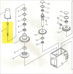
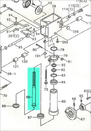
I'm curious because my prior RF-45 mill was a rattler & I always wondered why. The drawbar threads were a nice fit to the tooling. But additionally, It seemed to me that the drawbar (yellow) once installed was constrained (more or less fixed) on both ends once tightened. On the bottom end, once it pulls the tool against R8 seat, the drawbar engaged in threads, I don't think it can move laterally? On the drawbar top side, under the hexagonal tightening profile, was a slight tapered conical profile that mates & self center the (green) drive shaft part which I think had a mating chamfer. Kind of a shaft within a tube assembly. So assumed that end also becomes fixed. Therefore I always figured the rattle must be originating somewhere from the bearings/bushings external to these 2 components. But if your rattle went away, where exactly was the slack?
 

Attachments

  • EDT-2021-11-21 11.37.14 AM.jpg
    EDT-2021-11-21 11.37.14 AM.jpg
    94.6 KB · Views: 3
  • EDT-2021-11-21 11.37.45 AM.jpg
    EDT-2021-11-21 11.37.45 AM.jpg
    93.9 KB · Views: 3
Susquatch do you have a schematic or anything to elaborate on your fix? I cant quite determine where its located or buffering.

I'm curious because my prior RF-45 mill was a rattler & I always wondered why. The drawbar threads were a nice fit to the tooling. But additionally, It seemed to me that the drawbar (yellow) once installed was constrained (more or less fixed) on both ends once tightened. On the bottom end, once it pulls the tool against R8 seat, the drawbar engaged in threads, I don't think it can move laterally? On the drawbar top side, under the hexagonal tightening profile, was a slight tapered conical profile that mates & self center the (green) drive shaft part which I think had a mating chamfer. Kind of a shaft within a tube assembly. So assumed that end also becomes fixed. Therefore I always figured the rattle must be originating somewhere from the bearings/bushings external to these 2 components. But if your rattle went away, where exactly was the slack?

I don't have a drawing, I just fabbed it on the fly. I do a lot of things that way.

So, my rattle was at the top of the spindle. The threads in the R8 collet look after centering the bottom end.

I do not have a conical section at the top of the spindle. If I do, I can't see it. But here is photo of the bottom of the top of the draw bar on my Bridgeport.

20211121_143143.jpg


As you might be able to see, the bottom of the Drawbar at the top is flat. You can also see the original bushing.

There are two problems with the bushing.

1. The small collar at the bottom of the bushing is not a great fit to the inside of the spindle.

2. The ID of the bushing is sized to fit over the rolled threads at the bottom of the Drawbar, but the thread OD is much bigger than the Drawbar shaft. So the shaft is free to slide around inside the bushing and the bushing is free to slide around in the inside of the spindle. The result is a bar that vibrates as it spins. You can even see it wobble at the top when the spindle is spinning.

The original bushing had to be big in order to slide over the OD of the rolled threads. I solved that by sizing the bushing for the rod, not the threads, and then tapping the bushing for the threads. It means you have to screw the bushing on until it clears the thread, but no big deal.

There was no excuse for the small collar. I just made a better fit to the spindle for that.

All quiet as a church mouse now.
 
Hmmm..... I may have jumped to a premature conclusion that my RF45 maybe had some actual design thought behind it. I'm shocked (not). Maybe it was just a crude chamfer on the top of drive shaft & crude tool fillet on underside of hex & if they mated it was just blind luck. I followed some guys who CNC retrofitted this RF class mill, but usually the drawbar was either modified or gearbox gutted altogether with VFD conversion, o wasn't a fair comparison their noise completely went away. Well, this issue is potentially something to follow up on for anyone experiencing this annoying rattle.

Somewhat related, I discovered some of my R8 tooling was tapped a bit short relative to drawbar threads (or could be vise-versa drawbar length a smidge longer). Anyways, this is potential bad news because the drawbar can bottom out on the threads without the tool R8 taper actually mating the seat. Not a good thing to be running under power. So now with every new R8 tool acquisition, I carefully check beforehand.

It would be easy to install washers to compensate. I deliberately made the collar a bit short for that reason.
 
Yes, forgot to mention that - exactly what I did. Machined a washer/bushing.
Oh, and apparently it's not uncommon to discover that pulling the drawbar out for the first time is an unexpected encounter with ceiling drywall LOL
 
Yes, forgot to mention that - exactly what I did. Machined a washer/bushing.
Oh, and apparently it's not uncommon to discover that pulling the drawbar out for the first time is an unexpected encounter with ceiling drywall LOL

Ya, that's not a problem in my shop. 16 ft steel siding ceiling.

Otherwise I'm sure I would have! LOL!
 
Good solution @Susquatch.

I think the problem was not the loose fit of the collar, but rather the DB threads bottomed out in the collet as @PeterT is suggesting.

Why am I saying that? Well, if the DB was under proper tension, it would be highly unlikely that the shaft would have a chance to move radially inside the bushing. The collar is essentially sandwiched in there (between the bottom of the hex head and the top of the spindle). It’s like using a flat washer with an over sized hole under a nut or bolt head: they only rattle around as long as the bolt is not torqued. As soon as the system is tightened up, the washer(s) are pinched and don’t move any more.

My BP drawbar is different:

The treads are not rolled
17C6E0D8-89C7-4B24-9B19-4DDA30BBFE1F.jpeg


The bar is cylindrically ground.

The collar has an O-ring retaining it to the shoulder.
FB192916-5088-4F52-9D95-DB22F00426B7.jpeg


There is an oil hole in the center at the top and an exit hole on the side.
6861AB86-6E36-4B7C-BAEB-239203E53155.jpeg


Here is what it looks like fully assembled.
C1D8102D-DA8E-4BAF-9007-EC996D6A5462.jpeg


Yes it is quite loose radially in the spindle bore top. But it never rattles after tightening the collet. No conical features either. Totally flat.

I wonder if your DB is an aftermarket item?
 
I think the problem was not the loose fit of the collar, but rather the DB threads bottomed out in the collet as @PeterT is suggesting.

Why am I saying that? Well, if the DB was under proper tension, it would be highly unlikely that the shaft would have a chance to move radially inside the bushing. The collar is essentially sandwiched in there (between the bottom of the hex head and the top of the spindle). It’s like using a flat washer with an over sized hole under a nut or bolt head: they only rattle around as long as the bolt is not torqued. As soon as the system is tightened up, the washer(s) are pinched and don’t move any more.

I love how you think. Frankly, it's quite impressive. Never the obvious.

But I think you are not correct on this one. It would be a mistake to think that the drawbar is "rattling" inside the spindle. That assumption might be my fault for my choice of words. I don't think the draw bar moves inside the spindle much at all once it is tightened up even though it does wobble around a lot.

Rather, I think the off center draw bar creates an out of balance situation that causes a vibration that causes other things to rattle. I don't know exactly what is rattling. My best guess is that it's the play in the splines of the spindle inside the drive system. But it could be many other things too.

A couple of observations.

1. I am very careful to make sure that the drawbar is not bottomed out.
2. The end mill I used is loose in the collet until it is tightened and after tightening, it is never loose.
3. My Drawbar wobbled like crazy before my mods, and now it runs true as an arrow. When I say wobble, I don't mean loose or rattling itself. I mean it runs off center and appears to wobble. It's easy to see at low speeds.
4. Even with the drawbar removed, it is easy to rotate it back and forth and you can literally feel the spindle splines engaging the drive system.

My BP drawbar is different:

Yes it is quite loose radially in the spindle bore top. But it never rattles after tightening the collet. No conical features either. Totally flat.

Mine used to be loose before tightening, but not anymore. It's a good sliding fit now.

I wonder if your DB is an aftermarket item?

That is entirely possible. But as described above, that isn't the issue.

My fix did the job nicely.

And for what it's worth, even if my head didn't make any noise, I would still want to fix the wobble. It drove me nuts just looking at it.

A couple of questions:

1. What is the oil hole for? The exit hole appears to be above the spindle. Why do you want oil up there? Neither of mine has any oil holes.

2. What is the O-ring for? I read your comment that "The collar has an O-ring retaining it to the shoulder." What shoulder? I don't have an o-ring either.
 
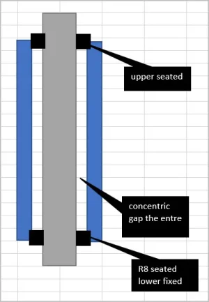
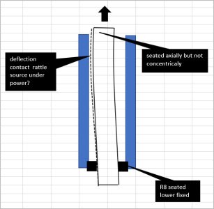
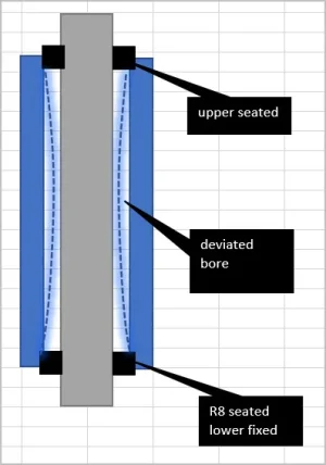
I wonder if this could happen. The original loose tolerance drawbar is free to drift off center within the spindle shaft hole. As its being tightened, it can end up with one side of drawbar OD closer to bore ID. Now under power, maybe any small amount of drawbar gyroscopic flex accounts for surface to surface contact = the rattling? Maybe the fix is not so much tightening up the end as ensuring the annular gap stays sufficient down the length so no drawbar contact can occur? I just cant see how rattling bearings or bushings could last very long if they were the culprits.

I had a similar hunch on my RF-45, where I assumed it was centered & secured both top & bottom. But I wondered if maybe the bore was deviated just a bit (necked down drilled poorly or whatever) so that any minor drawbar deflection mid span might be the rattle. Maybe I should have tried a layer of heat shrink tape or something to see if it snubbed the noise at all. Curiously the new Chinese RF45-ish machine at Modern was very much quieter. I wondered out loud if they figured out the issue or was a Thursday machine or they dropped in a nylon gear or...? I just haven't heard many stories of BP's with the same rattle issue.
 

Attachments

  • SNAG-2021-11-21 9.47.25 PM.webp
    SNAG-2021-11-21 9.47.25 PM.webp
    10.1 KB · Views: 3
  • SNAG-2021-11-21 9.47.41 PM.jpg
    SNAG-2021-11-21 9.47.41 PM.jpg
    39.8 KB · Views: 3
  • SNAG-2021-11-21 10.02.53 PM.webp
    SNAG-2021-11-21 10.02.53 PM.webp
    11.8 KB · Views: 3
I wonder if this could happen. The original loose tolerance drawbar is free to drift off center within the spindle shaft hole.

I think that your idea is indeed possible. Without doing any calculations, I can imagine the shaft - if mounted and tightened off center - flexing with enough centrifugal force - and vibrating harmonically - to touch the inner bore of the spindle. You might be right about that.

In my minds eye, I can see it acting like a big fat guitar string and touching it with your finger nail.

I'm a bit of a curious george. I'm never really happy to just fix things. I much prefer to understand them as well as fix them. I think that you and @RobinHood (and a few others - @Dabbler and @Brent H come to mind) all have the same mentality. Who knows, it might just be a characteristic of people who like machining!

I'll see if I can check on those possibilities - either mathematically or experimentally later today.

I just cant see how rattling bearings or bushings could last very long if they were the culprits.


Maybe I should have tried a layer of heat shrink tape or something to see if it snubbed the noise at all.

But I wondered if maybe the bore was deviated just a bit (necked down drilled poorly or whatever) so that any minor drawbar deflection mid span might be the rattle.

I really don't think it's a bearing or bushing noise. The sound quality simply doesn't match that.

I will try some tape on an unconstrained draw bar to see what happens and I'll also see if I can check the bore ID for necking down.

However, I still think that the most likely culprit is the clearance between the spindle splines and the top or bottom drive gear splines. (most likely bottom) I can make a very similar sound just by rocking/rotating the spindle back and forth by hand. Supporting that theory is the fact that it only knocks when there is no load and usually only when changing speeds. A loaded constant speed spindle never rattles.

Your drawings show the situation quite well in my opinion. Without a proper centering fit between the shaft and the spindle bore, the frictional forces ALWAYS force the drawbar head off center. I forget what this plate friction force is called. The whole idea of my threaded bushing was to eliminate the cumulative spaces between the drawbar shaft, bushing, and spindle bore in order to constrain the head to the center of the spindle bore so it couldn't wobble any more.

As a result, it looks better with no wobble and sounds better too.

I have read here about others with a similar "loose Drawbar" problem. I just can't find them anymore. If I could, I would send them a link.
 
Last edited:
Making a proper fitting centering bush for sure will keep the DB aligned properly. With your mod, you achieved that.

I misunderstood in that case: I really thought the DB was making the noise because it physically moved inside the spindle bore at the top end to cause metal to metal contact “rattle”.

Yes, the top of my DB does “wobble” around unless I carefully tighten it while it is centered in the spindle. Never makes any noise though.

I like what Peter is saying about the DB bending and then acting like a guitar string (your analogy) and possibly being the source of the rattle noise. Another thing that could cause the DB to bend like that is if the bushing shoulder(s) (well fitting or not) were not at 90* to the DB axis. As the DB is tightened, the angled shoulder would induce a deflection force and bend the DB shaft, possibly enough so that, when it is spinning with the spindle, centrifugal forces cause it to touch the spindle bore.


1. What is the oil hole for? The exit hole appears to be above the spindle. Why do you want oil up there?
It is to lubricate the drawbar splines (I think that is actually a mistake: it should be “spindle splines”). Here is the manual excerpt:

3304539C-33A9-441C-B97A-5E5B3DF92EC5.jpeg


Edit: after lowering the spindle by 2” the oil exits the side of the DB through the little hole. The oil is then at the top part of the splines. Gravity and centrifugal forces will do the rest next time the spindle is run.

2. What is the O-ring for? I read your comment that "The collar has an O-ring retaining it to the shoulder." What shoulder? I don't have an o-ring either.
C1B61DBB-3AFC-4D10-9CDF-F48F65B8B0E6.jpeg


It stops the collar from falling off the DB shaft when you first insert it into the spindle. It engages a small, raised shoulder on the BD shaft. (see red arrow). The O-ring also acts as an “ejector”: during tightening of the DB it compresses. When you back the DB off, it releases the collet with the help of a very light hammer tap.

8B8D9244-5802-4E28-8AA4-D80138186450.jpeg


Item 20 is the collar, 21 is the O-ring.
 
Last edited:
Making a proper fitting centering bush for sure will keep the DB aligned properly. With your mod, you achieved that.

I misunderstood in that case: I really thought the DB was making the noise because it physically moved inside the spindle bore at the top end to cause metal to metal contact “rattle”.

Yes, the top of my DB does “wobble” around unless I carefully tighten it while it is centered in the spindle. Never makes any noise though.

I like what Peter is saying about the DB bending and then acting like a guitar string (your analogy) and possibly being the source of the rattle noise. Another thing that could cause the DB to bend like that is if the bushing shoulder(s) (well fitting or not) were not at 90* to the DB axis. As the DB is tightened, the angled shoulder would induce a deflection force and bend the DB shaft, possibly enough so that, when it is spinning with the spindle, centrifugal forces cause it to touch the spindle bore.


It is to lubricate the drawbar splines (I think that is actually a mistake: it should be “spindle splines”). Here is the manual excerpt:

View attachment 18468

Edit: after lowering the spindle by 2” the oil exits the side of the DB through the little hole. The oil is then at the top part of the splines. Gravity and centrifugal forces will do the rest next time the spindle is run.


View attachment 18470

It stops the collar from falling off the DB shaft when you first insert it into the spindle. It engages a small, raised shoulder on the BD shaft. (see red arrow). The O-ring also acts as an “ejector”: during tightening of the DB it compresses. When you back the DB off, it releases the collet with the help of a very light hammer tap.

View attachment 18469

Item 20 is the collar, 21 is the O-ring.

Good stuff. Don't be too hard on yourself for misunderstanding. I even titled the thread "Draw bar Rattle". Prolly no point in me trying to do better next time but I'll try to do better next time.... LOL!

I like the idea of lubing the spindle splines a bit. I may modify my Drawbar accordingly.

The O-ring is another matter. I'm not too worried about removing the bushing. I'm tall enough to just reach over and pull it out. But it would be good to help remove the collet. It's not a huge problem on either mill of mine. I just loosen the draw bar a half dozen turns or so and then use a heavy plastic mallet. One light rap and be ready to catch the tool bit before it hits the table!

Thanks for all your help!
 
Maybe another ingredient to rattling is the drawbar section profile itself, not really reflected correctly on my simple sketches. The majority of DB, the lower portion, is skinny by comparison to the upper thicker portion with more mass. So imagine a skinny, flexible stick with a concentrated blob of weight on top. As it spinning & oscillating, its easy to visualize the upper portion tracing a wider path & bending the shaft outward. Left unconstrained in the spindle shaft hole, maybe this (upper) area is where the rattling originates from.

It would be interesting if you temporarily attached a sleeve of material on the DB just where it enters the hole just to test. Like some winds of electrical tape or softer durometer O-ring if you can squeeze it, so the radial gap is filled up. Then tighten DB with moderate torque without the special adapter part. If the noise stops its probably entirely an annulargap/ centering issue.
 
Back
Top