• Scam Alert. Members are reminded to NOT send money to buy anything. Don't buy things remote and have it shipped - go get it yourself, pay in person, and take your equipment with you. Scammers have burned people on this forum. Urgency, secrecy, excuses, selling for friend, newish members, FUD, are RED FLAGS. A video conference call is not adequate assurance. Face to face interactions are required. Please report suspicions to the forum admins. Stay Safe - anyone can get scammed.

DIY Mill

Manfred

Active Member
Premium Member
Seeking some advice. Happy to supply more info on what I have and where I plan on going.

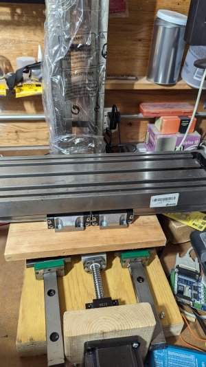
Attached some pictures of my DIY mill mock-up. Yes, most of it is still wood and its been like that for a while.

May have some time over the festive season and also decided rather than purchasing a (relatively) cheap 3D filament at Black Friday prices, that I would rather use the money towards my mill project.

As I said before the Z-axis column from an LMS5500 (11 3/4" travel 36lbs) and the table from a M1111 (6 1/4" x 21 5/8 38lbs). X-axis on Rexroth 20mm rail and y-axis on INA 30mm rails. Y is currently 22 inches - which I realize is damn long but I somehow can't get myself to cut the high quality rail. Comments? X-axis is a little longer than the table to allow me some extra movement. Still trying to figure out the z-axis. Can't decide whether to use the existing dove tails or use 20mm Rexroth rails.

Ball-screws are 16mm for x and y and 20 for Z. Closed loop steppers for all the axes, 4Nm NEMA 34 for x and y and 12Nm NEMA 34 for the Z-axis.

No plans to modify the table (yet), probably will end up reinforcing the Z-axis column in the future.

Spindle motor that I currently have is a 400W brushless NEMA 34. Might go to 1kW in future but that is still a way off.

Have been using Linux CNC and a Core2Quad PC to do some basic movements. No plans to change that or the motor drivers.

Question I now have is what size and weight base is appropriate for the machine. I've been thinking of a 10" x 26" x 1 1/2' cold rolled steel plate Blanchard ground on the top and drilling and tapping my own holes for the y-axis rails.

Took the concept to a machine shop in Oakville today and was told the base plate was overkill and that 1/2" inch thick would be good enough. Any comments / suggestions / blunt criticism appreciated.

Will Blanchard grinding be good enough or do I need the base to be surface ground?

Anything important that I've missed?
 

Attachments

  • PXL_20241128_150648260.MP.jpg
    PXL_20241128_150648260.MP.jpg
    1.6 MB · Views: 41
Seeking some advice. Happy to supply more info on what I have and where I plan on going.

Attached some pictures of my DIY mill mock-up. Yes, most of it is still wood and its been like that for a while.

May have some time over the festive season and also decided rather than purchasing a (relatively) cheap 3D filament at Black Friday prices, that I would rather use the money towards my mill project.

As I said before the Z-axis column from an LMS5500 (11 3/4" travel 36lbs) and the table from a M1111 (6 1/4" x 21 5/8 38lbs). X-axis on Rexroth 20mm rail and y-axis on INA 30mm rails. Y is currently 22 inches - which I realize is damn long but I somehow can't get myself to cut the high quality rail. Comments? X-axis is a little longer than the table to allow me some extra movement. Still trying to figure out the z-axis. Can't decide whether to use the existing dove tails or use 20mm Rexroth rails.

Ball-screws are 16mm for x and y and 20 for Z. Closed loop steppers for all the axes, 4Nm NEMA 34 for x and y and 12Nm NEMA 34 for the Z-axis.

No plans to modify the table (yet), probably will end up reinforcing the Z-axis column in the future.

Spindle motor that I currently have is a 400W brushless NEMA 34. Might go to 1kW in future but that is still a way off.

Have been using Linux CNC and a Core2Quad PC to do some basic movements. No plans to change that or the motor drivers.

Question I now have is what size and weight base is appropriate for the machine. I've been thinking of a 10" x 26" x 1 1/2' cold rolled steel plate Blanchard ground on the top and drilling and tapping my own holes for the y-axis rails.

Took the concept to a machine shop in Oakville today and was told the base plate was overkill and that 1/2" inch thick would be good enough. Any comments / suggestions / blunt criticism appreciated.

Will Blanchard grinding be good enough or do I need the base to be surface ground?

Anything important that I've missed?
The base plate should ideally provide dampening, so I dont think this is something to take lightly.

IF It were me I'd use 1/4" plate bolted into a shallow box and fill with epoxy granite, or just plain old cement.

Blanchard grinding can be accurate, if you fin it is not enough, you can scrape steel
 
Thanks for your thoughts. I like the idea of using epoxy granite / cement and initially agreed with your suggestion of the 1/4 inch plate. However, and this is not criticism but more how I'm iterating towards a solution, I have decided to use either 0.625" or .750" thick plate because I want to have two long grooves machined into the plate to position the rails when I mount them on the assumption that whoever does the machining will likely (hopefully) make a better job of ensuring they are parallel than I will. this reduces the amount of material available for the thread of the mounting screws to "bite" into on the plate. Plan on using C1080 cold rolled flat bar because it is flatter than hot rolled and pretty available. It is, however somewhat soft so that I will need between 1 to 2 times thread diameter for the M8 rail mounting bolts to hold on securely.

For those who are interested, here are the specs on the carriages and rails: https://medias.schaeffler.us/en/pro...emblies/carriages/kwve30-b/p/1956953#CAD Data

No, I did not buy them at the new price (approx. $350 per carriage - no idea what the rails would cost) and yes, they are somewhat over-dimensioned. :)

Here is the info on the rails: https://medias.schaeffler.us/en/pro...uideway-assemblies/guideways/tkvd30/p/1939191
 
I'm going to go out on a limb and throw my 2 cents in here as I feel I have some knowledge and a tiny bit of experience now with cnc mills, at least from the DIY conversion point of view.
First observation is that you are building with what is available and not what is near optimum (never seem to hit the mark ever - engineering is a compromise of many factors).
With that said, do you just want to build something for minimal cost or do you have some future plans for what its going to do. That influences things greatly.

Your 400w spindle motor is way underpowered for this size of machine. Your axis drive motors are probably 4 times stronger than it and will be able to drive the motion way faster than it can cut. You don't mention spindle type (taper) or the rpm it will run so I'll give you a hint - find a fast spindle - ideally 10000+ rpm (i.e. look at the spindle of the Tormach 770). A machine this size is big for a desk, but small from industry standpoint and would benefit from running smaller cutters at higher rpm to reduce loads / deflection. I just sold my RF45 variant CNC and it did not like big end mills (say above 1/2"), but I didn't have the spindle speed for small cutters (below 1/4") so I was left with a limited sweet spot of cutters to work with (6mm / 1/4" through 1/2" or so).

Don't get into analysis paralysis. Build something and try it. I may not be a fan boy of Elon Musk but one thing he has done is change the face of development. Build and test, don't analyze to death, put all your eggs in one basket and then cry if it doesn't work like you thought it would. Do it again with knowledge of what didn't work.

Don't use cold rolled and expect it to stay flat after the grooves are machined in, those grooves will help it curl by releasing surface tension. Use hot rolled, it'll be cheaper too. You only need the grooves to be nice and parallel, the rest will be painted, and you could even then embed the lower half in some epoxy granite for more mass and support. Speaking of support - how will you affix the column? While having the grooves machined add mounting locations for the column.

Also, on you control - linux cnc and a breakout board via parallel port is fine for testing, but you will be severely limited in speed and resolution. You'll never get near the capabilities of you stepper motors speeds, or you will have to give up step resolution to do so. You can keep LinuxCNC and get a Mesa card (ethernet connection type) to enable the full speed of the machine and it'll give you more I/O options than you can possibly imagine (home and limit switches and relays to the moon and back).

There's probably more but that's my first glance at this.
Thank you for your input.

Yes, I'm building with what is available. The mechanical bits were mostly purchased on ebay.

The 400W spindle motor came along with the two smaller steppers for free; that's why it is currently the spindle motor - essentially by default. I do understand that it is seriously underpowered compared to the rest of the machine.

I don't think I'm creating a case of analysis paralysis. I have an idea were I would like to get to and am testing components and ideas as I am going along. Importantly, I am also listening and learning from others. For example, what you are saying about machining the cold rolled makes a lot of sense. One reason I was going to use the cold rolled is because a machine shop in Oakville suggested that and the finish is much better by default - however what you are saying makes more sense to me. Probably will go for the hot rolled. Might even look at a thick walled rectangular tube and fill it with epoxy.

I am currently using LinuxCNC and a breakout board for testing because it is available and the learning curve for me is significantly less steep than using a Mesa card. I quite look forward to (having to) figure out the Mesa card but don't have the time and inclination to do so now. Besides, the breakout board is much cheaper and is easy to figure out.

That is also one reason why I am doing some analysis on some of my options such as the steel base plate. It's a lot cheaper and efficient to think and ask for advice / suggestions than charging forward. For example I purchased a 1/2 inch cold rolled steel plate for my base a few years back. That is too curved and frankly too light to be suitable. Still holding on to it because I'll probably need it for another of my crazy ideas. Another reason for making judicious choices is that I do cannot do any of the machining myself which makes the whole endevour rather espensive. For example, I was quoted around $250 by the machine shop in Oakville just to drill and tap about 20 holes for the linear rails. No machining at all. The Blanchard grinding would have been subcontracted - you live and learn.

As to mounting the z-column, the location for the base will be machined same time as the grooves for the rails and the ball bearing supports for the ball screws and the motor support.

While I'm at it I'm also developing a working knowledge of Fusion 360.

Hope my tome did not come across as being defensive, I'm explaining my rationale and the trade-offs that I am making. With some luck this will be of some value to the next person walking this path.
 
I plan on initially using a Taig spindle, perhaps with higher speed bearings and modified for an ER20 collet. For power I'll try the 400W brushless or a 1hp DC motor off an old tile saw.

Depending on how that goes, or just for the hell of it, I am considering a modified version of the Little Machine Shop spindle as used on the SIEG X2-R8 Mini Mill. https://littlemachineshop.com/products/product_view.php?ProductID=1944&category=
 
No offense taken, I'm just giving my thoughts.
The Taig spindle should be good to ~7000 RPM, much higher than the LMS spindle will do (looks like 2500rpm). A lesson I learned about spindles is that its not just the bearings, or even the balance that is the issue with higher speeds, its also the seals and lubrication. You can switch to higher speed rated bearings but if you can't keep them clean and lubricated they will fail. Thing is that the seals are much harder to design and fit for higher speeds. Trying to run a low speed spindle much faster with higher speed bearings will usually result in a burnt or melted seal at a minimum. Also a low speed spindle may be using a simple bearing configuration for lowest cost, but that configuration will not work well at higher speeds due to thermal growth. And the lubrication spec for lower speeds is usually not appropriate for higher speeds. Lots of fun can be had trying to figure it all out. But first you need to decide your tool retention method then you can pick a spindle. If you plan ahead (way far ahead), pick a type that allows Automatic Tool Changes. That way you can add it later and not need to get all new holders. BT30 is a reasonable choice for this (commercially available ATC spindles, abundant ecosystem of holders out there at reasonable cost).
 
The base plate should ideally provide dampening, so I dont think this is something to take lightly.

IF It were me I'd use 1/4" plate bolted into a shallow box and fill with epoxy granite, or just plain old cement.

Blanchard grinding can be accurate, if you fin it is not enough, you can scrape steel


When I've thought of such a project (eventually I sobor up lol), it ends up being welded boxy shapes for strength and an epoxy granite fill. Its stable and has twice the damping of cast iron. Damping is a function the boundary between two dissimilar materials (the resin and the sand) and its very stable. I don't know what the damping of concrete, suspect its not great, but it aslo never stops moving. Literally, its keeps curing. The weldment is a inexpensive way to get any size and shape and will be very strong. By itself its not great as it rings like a bell .... but with the EG.... you'll be just like Hardinge :) I would have it run through a heat treatment place to normalize it before scraping/ginding/machining.

The other thing to keep in mind is linear rails don't absolve one from figuring out how to get accurate machien tool gemeotry. They will curve to whatever they are bolted so, so it has to flat. Its hard to get big things flat. i.e. A piece of cold rolled blanchard ground for example will turn in banana shape once the mag chuck has been released, unless its been carefully stress relieve first. Even then. This where scraping comes into it.

To Mikes point, as a project/labour of love/quest etc, have at it. But don't expect it to be less expensive or perform at the level of that what you can buy used. Without any machine tools, that might be a first move to consider.
I always forget to mention stress relieving as a necessity.
 
When I've thought of such a project (eventually I sobor up lol), it ends up being welded boxy shapes for strength and an epoxy granite fill. Its stable and has twice the damping of cast iron. Damping is a function the boundary between two dissimilar materials (the resin and the sand) and its very stable. I don't know what the damping of concrete, suspect its not great, but it aslo never stops moving. Literally, its keeps curing. The weldment is a inexpensive way to get any size and shape and will be very strong. By itself its not great as it rings like a bell .... but with the EG.... you'll be just like Hardinge :) I would have it run through a heat treatment place to normalize it before scraping/ginding/machining.

FWIW, I think there are two kinds of damping being discussed here. One, as you say is at the boundary between two materials, and the other is throughout the grain structure of heavy masses. Some materials are better than others. Depending largely on the frequencies and amplitudes involved, Sand, gravel, and concrete can all be very effective.
 
Damping is a characteristic on how fast a wave decays in the material. My understanding is that happens at the boundary layer between dissimilar materials - i.e. sand/epoxy and I guess sand/air. i.e. if you put a wave into something, how quickly it decays is damping. I see what you saying, a really massive object will move less with vibration, but I don't that is damping .... i.e. mass would mean the wave was smaller for a given input in the first place vs how fast the wave decays. It might be splitting hairs if it gets you to the same spot. i.e. My 5000lb cast iron lathe does a better job of not vibrating compared to 7x12 although both are cast iron.

Anyway, I long exhausted my inclination to research vibration, damping and decay rates ..... but I do recall seeing graphs that cast iron had about twice the damping of steel, and that EG had about twice damping of cast iron. Those are the (imo) important bits I've carried with me through any machinations of machine design.

Technically, epoxy granite is a concrete, e.g. Hardinge calls Harcrete. I don't know what the damping properties of cement-based concrete are vs EG, but would guess it a lot less as I'd suspect you could describe the materials in EG as being more dissimilar. However, imo its moot as unlike EG portland concrete keeps moving making it not a great choice for a precision machine's frame.

The other thing to consider, is that a cross section is likely to have a lot more EG than steel ..... so while EG is not as rigid as steel, the large quantity of it (compared to say a steel exoskeleton) ius a significant contributor to strength and rigidity. Some guys make machines just from casting parts (I don't have data to dispel that approach, but I’d be more comfortable with a steel exoskeleton)
 
Last edited:
Damping is a characteristic on how fast a wave decays in the material.

That's what I was trying to get at Mike. That's only one definition. I don't think you or anyone else here wants to endure a full course on Vibration Theory. I probably have a dozen Engineering Textbooks on the subject. I'm happy to loan them to anyone who is interested.

Some readers might want to scroll to the end of this "short" discussion to see my summary and advice.

Unfortunately, I don't think I really have a fast way to give the highlights at a sufficient level to provide understanding. But I can at least try to provide some insights.

To begin to understand damping, I think you first need to understand vibration. Most of us probably think of vibration as cyclical movements of assemblies, parts, or particles/molecules in a larger elastic body - remember that in machining, everything is rubber. These vibrations can be regular and deterministic (can be defined by a formula), or random and best described statistically.

In all cases these motions follow the laws of basic science where Force=Mass x Acceleration. Everyone familiar with calculus understands that Velocity is the rate of change of the displacement (movement) of an object, whereas acceleration is the rate of change of its velocity.

Movements and displacement do not need to be cyclical (sinusoidal). But in machining, they usually are.

At its most fundamental level, damping as it applies to the mechanical vibration of our machine tools is the process of dissipating energy to control, reduce, or prevent vibratory motions. If the damping force exceeds the input forces, it can prevent vibrations entirely, if not it merely controls them.

Damping forces are a special type of force that are typically used to slow down or stop a motion. It's easy to relate this to the shock absorbers in a vehicle's suspension as classical dampers that prevent the suspension from vibrating out of control when excited by a bump in the road. But again, in machining, that motion can be the entire machine, a component of it, or as the molecules and particles within a given component. The key point here is that damping forces restrict the vibrations by counteracting (acting against) the forces that create them.

It doesn't really matter a lot where or how these damping forces occur, what is important is their effectiveness.

Although I could be wrong, I have the impression that you have zeroed in on the classical energy absorbing damping that takes place due to friction at a boundary layer between two materials in relative motion to each other. It is a familiar form of damping. Think of this as the piston in the shock absorber I mentioned earlier experiencing friction at their interface. Or as the friction in a sway bar control on the hitch of a trailer. In both these cases, the friction transforms the energy into heat at the interface. But if we change the design into a more effective hydraulic shock absorber, it is the force of moving fluids from one end to the other through controlled orifices that dissapates energy by heating the oil as it is forced through the orifices.

What is less obvious is the very large resistance and energy absorbing characteristics of a dense medium in a composite material. The damping force of concrete is a process that occurs when the composite material undergoes changes in stress and strain over time resulting in a loss of mechanical energy. This energy is usually transformed into thermal energy in the concrete itself. The same principles apply to stuff like sand and gravel, epoxy granite, or cast iron. In a very simplistic way, you can think of it a bit like a million distributed surfaces moving relative to each other. It's work done on the material itself.

This energy dissapation can be much larger than interfacial dissipation because vastly larger magnitudes (volume vs surface) are involved - just like a hydraulic damper vs a friction damper.

The really interesting part of this discussion has its roots in the frequency response of the materials and surfaces. Different materials with different granular structures can have a very different damping characteristic that very much depends on both the frequency, and magnitude of the motions. Beyond that, the size and mass determine the magnitude of resulting movements, but also affects its natural frequency.

Coming back to the subject at hand, I very much agree that interface friction is an important factor in controlling vibrations, but so is the mass and overall structure of damping masses. Which is more important in each case would be a purely academic exercise that would boil down to analysing the frequency responses of each and the magnitude of their respective energy dissipation across the encountered spectrum. In most machining cases, I'd wager good money that it's easier to add mass and energy absorption volume than it is to design effective frictional interfaces. One cannot simply say that any one approach is more effective because "It all depends!"

As it relates to the subject design, I think it is also important to recognize that the damping forces are additive. That's exactly why it can't hurt to pour concrete or EG into the base or post or internal cavities of a machine. Yes, it will move over time as the materials cure, but that's yet another reason to be judicial about where these materials are applied as well as to be rigorous about performing regular inspections and adjustments.

In summary, add as much damping components as is reasonable for the application. They all add together. It's also hard to overestimate the value of mass. The bigger, the heavier, the better. At the frequencies and amplitudes encountered in most machining operations, steel isn't very good, cast iron is ok, course aggregates and sand works better, concrete is better still, and Epoxy Granite is best. All will make a difference, but don't be surprised if the end result isn't what you expected. That's because the frequency and amplitude of the input vibration matters very much and the system response is even more important. Unless you do the analysis for each case, and understand the implications for your machine, it's very hard to choose what to do. I like the broad brush approach simply because each component of any solution is additive. That's basically why it works.
 
From which I deduce, amongst a number of other insights, that, while I need to keep my options open as far as possible, it will make a big difference whether I am using a relatively light, high speed spindle or a large (by my standards) R8 based spindle that will likely spin at about a third or quarter of the speed. The input frequencies will be very different and so will the system response.

My focus for now will thus be on getting the X and Y axes moving without breaking the bank or backing myself into too small a corner technically.

Really, on a DIY project just consider this, with a proper structural skeleton and any decent blend of epoxy granite you will obtain better dampening than can be had with a steel tube frame and steel plate bed regardless of the spindle frequency and size.

Let me add this too as a designer. Set your goals and parameters prior to anything else or expect failure, disappointment and greatly increased costs.

Can you articulate clearly what you want your mill to be capable of?

For my build which I call a router I have the following requirements:

Working envelope as large as possible (30" x 30" x 5") based on a 24 x 36 granite base plate and the ability to cut longer pieces via pass thru design.

Ability to cut wood, plastics, aluminum, brass and steel (very slowly)

Those seemingly limited criteria dictate basically everything else, type of structure, work holding system, size of rails and stepper motors, and spindle size.

What do you want to do with this mill?
 
That's what I was trying to get at Mike. That's only one definition. I don't think you or anyone else here wants to endure a full course on Vibration Theory. I probably have a dozen Engineering Textbooks on the subject. I'm happy to loan them to anyone who is interested.

Some readers might want to scroll to the end of this "short" discussion to see my summary and advice.

Unfortunately, I don't think I really have a fast way to give the highlights at a sufficient level to provide understanding. But I can at least try to provide some insights.

To begin to understand damping, I think you first need to understand vibration. Most of us probably think of vibration as cyclical movements of assemblies, parts, or particles/molecules in a larger elastic body - remember that in machining, everything is rubber. These vibrations can be regular and deterministic (can be defined by a formula), or random and best described statistically.

In all cases these motions follow the laws of basic science where Force=Mass x Acceleration. Everyone familiar with calculus understands that Velocity is the rate of change of the displacement (movement) of an object, whereas acceleration is the rate of change of its velocity.

Movements and displacement do not need to be cyclical (sinusoidal). But in machining, they usually are.

At its most fundamental level, damping as it applies to the mechanical vibration of our machine tools is the process of dissipating energy to control, reduce, or prevent vibratory motions. If the damping force exceeds the input forces, it can prevent vibrations entirely, if not it merely controls them.

Damping forces are a special type of force that are typically used to slow down or stop a motion. It's easy to relate this to the shock absorbers in a vehicle's suspension as classical dampers that prevent the suspension from vibrating out of control when excited by a bump in the road. But again, in machining, that motion can be the entire machine, a component of it, or as the molecules and particles within a given component. The key point here is that damping forces restrict the vibrations by counteracting (acting against) the forces that create them.

It doesn't really matter a lot where or how these damping forces occur, what is important is their effectiveness.

Although I could be wrong, I have the impression that you have zeroed in on the classical energy absorbing damping that takes place due to friction at a boundary layer between two materials in relative motion to each other. It is a familiar form of damping. Think of this as the piston in the shock absorber I mentioned earlier experiencing friction at their interface. Or as the friction in a sway bar control on the hitch of a trailer. In both these cases, the friction transforms the energy into heat at the interface. But if we change the design into a more effective hydraulic shock absorber, it is the force of moving fluids from one end to the other through controlled orifices that dissapates energy by heating the oil as it is forced through the orifices.

What is less obvious is the very large resistance and energy absorbing characteristics of a dense medium in a composite material. The damping force of concrete is a process that occurs when the composite material undergoes changes in stress and strain over time resulting in a loss of mechanical energy. This energy is usually transformed into thermal energy in the concrete itself. The same principles apply to stuff like sand and gravel, epoxy granite, or cast iron. In a very simplistic way, you can think of it a bit like a million distributed surfaces moving relative to each other. It's work done on the material itself.

This energy dissapation can be much larger than interfacial dissipation because vastly larger magnitudes (volume vs surface) are involved - just like a hydraulic damper vs a friction damper.

The really interesting part of this discussion has its roots in the frequency response of the materials and surfaces. Different materials with different granular structures can have a very different damping characteristic that very much depends on both the frequency, and magnitude of the motions. Beyond that, the size and mass determine the magnitude of resulting movements, but also affects its natural frequency.

Coming back to the subject at hand, I very much agree that interface friction is an important factor in controlling vibrations, but so is the mass and overall structure of damping masses. Which is more important in each case would be a purely academic exercise that would boil down to analysing the frequency responses of each and the magnitude of their respective energy dissipation across the encountered spectrum. In most machining cases, I'd wager good money that it's easier to add mass and energy absorption volume than it is to design effective frictional interfaces. One cannot simply say that any one approach is more effective because "It all depends!"

As it relates to the subject design, I think it is also important to recognize that the damping forces are additive. That's exactly why it can't hurt to pour concrete or EG into the base or post or internal cavities of a machine. Yes, it will move over time as the materials cure, but that's yet another reason to be judicial about where these materials are applied as well as to be rigorous about performing regular inspections and adjustments.

In summary, add as much damping components as is reasonable for the application. They all add together. It's also hard to overestimate the value of mass. The bigger, the heavier, the better. At the frequencies and amplitudes encountered in most machining operations, steel isn't very good, cast iron is ok, course aggregates and sand works better, concrete is better still, and Epoxy Granite is best. All will make a difference, but don't be surprised if the end result isn't what you expected. That's because the frequency and amplitude of the input vibration matters very much and the system response is even more important. Unless you do the analysis for each case, and understand the implications for your machine, it's very hard to choose what to do. I like the broad brush approach simply because each component of any solution is additive. That's basically why it works.
There are a couple of other points worth mentioning.

To be a vibration, there must be some sort of repeating pattern ;) For a lathe or a mill, the tool is constantly 'ripping' parts of the stock, and each time a chunk is ripped off, the load pattern changes. That sudden change generates an impulse that travels through the frame of the machine as it changes shape to support the new loads. A vibration is some kind of repeating pattern of these impulses - a wave of waves!

This is a great example where it is far more useful to calculate in terms of energy than in reaction force. The specific reaction forces are very complex, and will change greatly for each work piece, tool and cut. But the total energy dissipation can be readily estimated - the source is the motor, and all the power that goes in has to come out somewhere. Most of it will go to waste heat in the stock, chips and tool, but a portion is dissipated this way. You can estimate how much energy you need to dissipate by assuming some reasonable upper bound like 5%

If it also possible to calculate how much energy a given material can absorb based on it's volume. Yes the shape matters because it affects how the vibrations propagate and the ability to absorb the energy, but to define an envelope, a single co-efficient is reasonably effective. There are table by mass or volume for different materials

As to why steel is poor, and other materials are better, steel is relatively flexible and more elastic. A lot of the energy that deforms it is converted to elastic potential energy and returned to the system instead of being converted into heat. Sand is an emulsion of stone and air / water and concrete is a more rigid version of the same

I'm sure there are other factors i'm forgetting, but I hope this helps
 
There are a couple of other points worth mentioning.

To be a vibration, there must be some sort of repeating pattern ;) For a lathe or a mill, the tool is constantly 'ripping' parts of the stock, and each time a chunk is ripped off, the load pattern changes. That sudden change generates an impulse that travels through the frame of the machine as it changes shape to support the new loads. A vibration is some kind of repeating pattern of these impulses - a wave of waves!

.........

As to why steel is poor, and other materials are better, steel is relatively flexible and more elastic. A lot of the energy that deforms it is converted to elastic potential energy and returned to the system instead of being converted into heat. Sand is an emulsion of stone and air / water and concrete is a more rigid version of the same

I'm sure there are other factors i'm forgetting, but I hope this helps

I think it's a good addition. I was reluctant to write too much which means I had to be judicious about what I covered and didn't cover. So it's nice for other knowledgeable members to read my short document and then identify and expand on other important aspects I didn't include.

The whole issue of machine rigidity is one that is far too often ignored because machinists equate rigidity and strength. The best example I can think of off the cuff is the design and fabrication of a machine stand. Users instinctively focus on strength - it has to be strong enough to hold my bench mill without bending excessively or collapsing in use. Next, they focus on utility - adding drawers and storage to the stand. Clearly, these are worthy and important goals. Unfortunately, it's very rare to see rigidity and machine damping considered as an equally important part of the design. But, I'd place its importance much higher than storage. Fortunately, it isn't necessary to give up storage to get rigidity.

The importance of stand rigidity and damping is one of my pet peeves. So I better shut up now.

Thanks for chiming in.
 
You're just setting me up for the next time I say something stupid ;)

But I think the most important point here is that when building a mill, you need to think about an envelope of performance. Even on a production machine that is repetitively doing only one job, there is a level of variability. But for a hobby machine, you would expect to do a wide range of things, and the variation is much higher

A certain amount of power on one hand, versus a certain frequency spectrum on the other. And probably the power is the most important part after the geometry itself
 
At my school there was a single span concrete pedestrian bridge that spanned a four lane highway. At the middle of the bridge was a lamp post mounted to the ground about a meter from the bridge. This served as a handy reference for the height of the bridge above the road. All it took was two or more teenage boys to jump up on the center of the bridge a few times at the right frequency and this bridge would move up and down by at least two feet - I remember more but won't insist on it. At one stage the city closed the bridge to pedestrian traffic and placed 50kg cement bags three high and two wide along the entire bridge. Nothing happened. Much better illustration of the difference between strength an rigidity than any theoretical discourse my engineering professors came up with.

While on a somewhat larger scale than most of our machines, the fate of the bridge illustrates the difference between strength and rigidity very well (accepting a few other technical details such as the aerodynamic effects of the wind). While certainly strong enough to carry the weight of the traffic, the bridge was simply too flexible for its environment and the forces acting on it. https://wsdot.wa.gov/tnbhistory/bri...Bridge stunned everyone, especially engineers.

Here's the accompanying video:
 
It's not rigidity that makes CI better at damping, its the boundary layers between dissimilar material within it- i.e. the nodular structure of cast iron. Steel actually has a slightly higher Youngs modulus than CI. There's other factors as per the bridge example, the natural frequency of the structure, but all things being equal, materials with lots of surface area (boundary layers) between dissimilar materials will damp the best (decay the wave, i.e. the amplitude is reduced more quickly)
 
Great discussion guys, so for stands or benches that our machines are mounted on, is there any remedial modifications that can be done to help dampen vibration?
I mounted my 80gal compressor tank on hockey pucks and it seemed to help a lot.
 
Back
Top