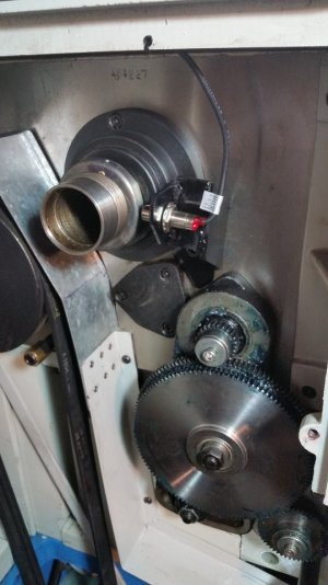
After converting my lathe to a 3 phase motor and VFD I decided to install a cheap digital tachometer on the spindle to allow me to monitor the spindle speed at any VFD frequency setting. I picked up the kit on Amazon but you can get them on Ali Express or eBay also.
https://www.amazon.ca/DIGITEN-Digital-Tachometer-Proximity-Switch/dp/B00VKAT8A2/ref=sr_1_10?crid=3V0O58CEC1084&dchild=1&keywords=digital+tachometer+rpm+meter&qid=1604947575&sprefix=digital+tach,aps,217&sr=8-10
It came with the digital display panel and a hall-effect sensor speed pickup with a magnet. I machined a steel ring with and ID to slip over the threads on the left end of the spindle so it could be held in place with a M5 set screw. To keep the set screw from damaging the threads I machined a 1/2 round slot with a brass key that lines up with the screw. Then I milled a pocket to hold the magnet and epoxied it in place on the OD of the ring.


I put together a bracket to hold the hall-effect sensor to line up with the magnet.


I set the clearance between the sensor and the magnet at .060" and ran the wires up to the VFD cabinet. I cut a rectangular hole in the cabinet door to fit the display and connected the wiring as per the instructions. It works like a charm. I have been checking the magnet ring for any sign of the magnet coming loose or the set screw backing out and there have been no problems after about 20 hours of use.


The speed chart for this gear setting on the lathe says the rpm should be 910 but the display shows 963 which I have verified is accurate with a hand held tachometer. A fun little project for these boring COVID distancing days.
https://www.amazon.ca/DIGITEN-Digital-Tachometer-Proximity-Switch/dp/B00VKAT8A2/ref=sr_1_10?crid=3V0O58CEC1084&dchild=1&keywords=digital+tachometer+rpm+meter&qid=1604947575&sprefix=digital+tach,aps,217&sr=8-10
It came with the digital display panel and a hall-effect sensor speed pickup with a magnet. I machined a steel ring with and ID to slip over the threads on the left end of the spindle so it could be held in place with a M5 set screw. To keep the set screw from damaging the threads I machined a 1/2 round slot with a brass key that lines up with the screw. Then I milled a pocket to hold the magnet and epoxied it in place on the OD of the ring.


I put together a bracket to hold the hall-effect sensor to line up with the magnet.


I set the clearance between the sensor and the magnet at .060" and ran the wires up to the VFD cabinet. I cut a rectangular hole in the cabinet door to fit the display and connected the wiring as per the instructions. It works like a charm. I have been checking the magnet ring for any sign of the magnet coming loose or the set screw backing out and there have been no problems after about 20 hours of use.


The speed chart for this gear setting on the lathe says the rpm should be 910 but the display shows 963 which I have verified is accurate with a hand held tachometer. A fun little project for these boring COVID distancing days.

