• Scam Alert. Members are reminded to NOT send money to buy anything. Don't buy things remote and have it shipped - go get it yourself, pay in person, and take your equipment with you. Scammers have burned people on this forum. Urgency, secrecy, excuses, selling for friend, newish members, FUD, are RED FLAGS. A video conference call is not adequate assurance. Face to face interactions are required. Please report suspicions to the forum admins. Stay Safe - anyone can get scammed.

Tips/Techniques Dan Gelbart shows how to test lathes and mills

Tips/Techniques
Dan Gelbart in his bat cave discusses how to test lathes and mills. Of course his equipment is amazing (and pricey!). CNC gear but with manual handles for all the axis. I almost hate to try these tests on my machines. Performing these tests while inspecting a potential purchase could be quite helpful. Maybe I'll try a few of those tests and post results - be interesting to see results from other members.

He also explains the advantages of the 3D metal printer he designed. Maybe the forum could buy one! just $200K. Really good content from Dan as usual.

EDIT dec 2023-> Dan has deleted this video as he was not happy with it. You can read the thread still and get a feel for most of the testing from the video.


Last edited:
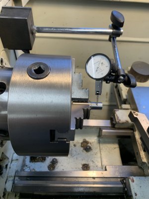
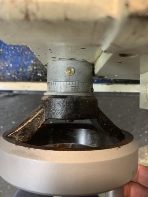
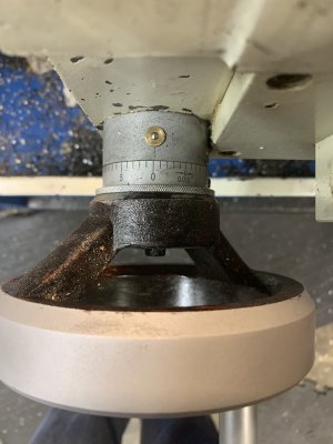
Ok I’m trying the first test he showed which illustrates how round your lathe is turning. I turned a lump of ground drill stock and then sanded it with 80 and 400.

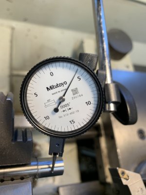
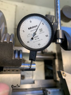
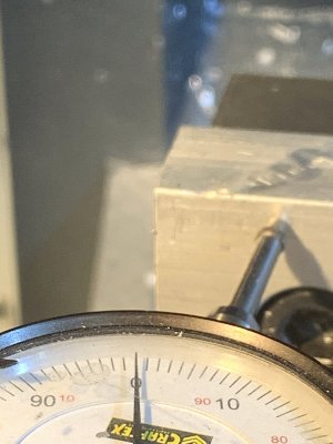
I got out the 0.0005 dial indicator. I don’t have a 1 micron indicator - roll eyes. The two pictures show the dial indicator with the min and max deflection. I read that as maybe 10% of the graduations. 0.00005”?

Dan’s is 1 micron which is about 0.00004” or an order of magnitude better.

0.00005” C0636
0.000004” Dan Gelbart's

My lathe is C0636 modern tool 14x40. I bought it used a few years back. I am actually quite impressed considering I bought it for about $3700. Good and fortunate timing not bragging. I got lucky. This was before everything went up so much. How about your lathe? @johnnielsen how about your big German iron? I imagine it's a lot better. @kevin.decelles you have the newer version of the C0636 try yours! @Dabbler please try your Monarch Leblond. Bert's lathe - that's a monarch isn't it? Somebody on here has a 10EE. Try yours.
 

Attachments

  • D30EC63E-E05E-4CE8-B05B-36DA7C06C478.jpeg
    D30EC63E-E05E-4CE8-B05B-36DA7C06C478.jpeg
    231.2 KB · Views: 12
  • A7B41597-FF38-48AA-BC0C-1E9E108AAC36.jpeg
    A7B41597-FF38-48AA-BC0C-1E9E108AAC36.jpeg
    267 KB · Views: 12
  • 60E1CE0F-FD87-4A62-89BE-BB4DC0248DFA.jpeg
    60E1CE0F-FD87-4A62-89BE-BB4DC0248DFA.jpeg
    312.4 KB · Views: 12
Last edited:
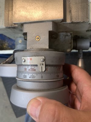
ok now I'm trying the spring test to see how much the spindle bends under load. I didn't make a 100kg spring, instead I just pushed hard on the chuck while watching the dial indicator to see how much deflection there is. The dial indicator moves about one graduation when I push as hard as I can. That's 0.0005"
0.0005" C0636
0.00012" <- Dan Gelbart's is 3 microns

That is still a good result. I guess half a thou is way under what I can manage maybe I can hit with a few thousandths if I'm trying hard. On a good day... With no mistakes.... :)

0.0000393" is 1 micron. Somebody check my math.
 

Attachments

  • 80632FB4-4D1E-4AFF-AD5C-75B156B3DD53.jpeg
    80632FB4-4D1E-4AFF-AD5C-75B156B3DD53.jpeg
    436.6 KB · Views: 21
Last edited:
I saw this video some time ago but he lost me right from the beginning with his spring. How do you make one and how do you calibrate it for the proper force? He says simple tools but he doesn't explain any thing about this "simple" spring ie how can someone make one.
 
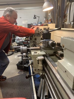
I don't think his spring is all that accurate. He just said bend this cold roll in half and put in a threaded rod for convenience to hold it together. The point though is to put a big load on the spindle and see if it moves. if it moved lots like say 10 thou 0.010" then the spindle bearings are bad or loose worn or something like that. 100kg is like stepping on it. If it holds you up then it's at least 100kg. good enough. I added a picture of me pushing.
 
Last edited:
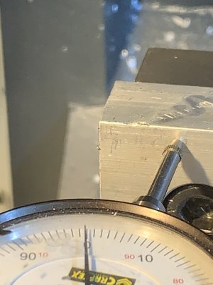
OMG this is fun. Can you say GEEK! haha now I'm trying his backlash tests. How much back lash in the lead screw and in the cross slide?

Lead screw backlash
0.030" C0636
0.0001" HAAS Mill Y axis - actually less than this it's hard to see.
0.000012" Dan Gelbert he says 3 microns on his fancy lathe with ball screws just by pushing.
0.00006" with his 100kg spring it is 15 microns.

Cross slide backlash
0.0025" C0636
" HAAS Mill X axis - can't get a measurement as it much more awkward to push to the side.
Dan didn't say what his cross slide backlash was.

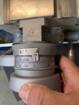
I don't know how to measure lead screw backlash. I just estimated by seeing how much the dial wiggles without moving the carriage. Is there a better way?

That backlash of 0.030" on my lathe that seems like a lot to me. Is it?
 

Attachments

  • 0355653C-3A60-48DC-B34B-523D535E33AA.jpeg
    0355653C-3A60-48DC-B34B-523D535E33AA.jpeg
    263.9 KB · Views: 8
  • 54B58933-73E7-4510-90DA-BC089A57D300.jpeg
    54B58933-73E7-4510-90DA-BC089A57D300.jpeg
    274.2 KB · Views: 9
  • D6FE45ED-13E4-4BE1-94B1-14C22FE52E7D.jpeg
    D6FE45ED-13E4-4BE1-94B1-14C22FE52E7D.jpeg
    344.5 KB · Views: 11
  • F7EBEEDB-9782-43A1-8234-D7FAB8BCAE91.jpeg
    F7EBEEDB-9782-43A1-8234-D7FAB8BCAE91.jpeg
    269.5 KB · Views: 10
  • E4E90320-4EFB-4ACF-A9A7-AC8B18ADFB54.jpeg
    E4E90320-4EFB-4ACF-A9A7-AC8B18ADFB54.jpeg
    305.8 KB · Views: 8
  • C8111144-CFAC-4B0D-BA1A-0A3B1B09E80D.jpeg
    C8111144-CFAC-4B0D-BA1A-0A3B1B09E80D.jpeg
    336.8 KB · Views: 9
Last edited:
Spindle test :rolleyes: first error, all you are measuring is if your jaws (scrolling) are centered to spindle, think about it. This can easily corrected for a specific dia (ie test bar) be grinding the jaws at that dia.

The pressure test is not so much the spindle but the fllex in your head stock/bed mount and its relationship to where the indicator is mounted.
 
That backlash of 0.030" on my lathe that seems like a lot to me. Is it?
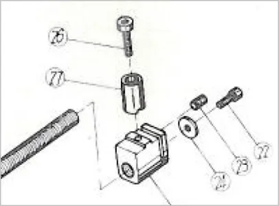
Mine was getting up there this summer. I was able to adjust the feed screw anti-backlash nut a bit more to get some more life out of it. But I can also see wear in the feed screw itself over the predominant segment. I have a new replacement set that will go in together pretty soon. I paused to CAD up a different (auto adjust) ABL nut based on some ideas I've seen, but the physical size, how it mounts & physical constraints make some of the compensating mechanisms more challenging to fit. The ABL I have (slot & pinch screw method in pic) is kind of low brow but it works. So rather than get fancy I could just make some spares & toss them. But the leadscrew wear was a bit of eye opener though. Slop in either component both contribute to total slop. I guess I assumed maybe replace 3 ABL's to 1 leadscrew based on the 2 materials, but maybe that's not the case.

Anyway, with DRO you can tolerate a bit more backlash, because you are watching the readout not the handle to get into position. But this presumes you lock the ways so it stays put. If table does not have a lock, increasing backlash is an increasing bad thing from a general machining perspective (accuracy, finish, chatter...).
 

Attachments

  • SNAG-2022-11-11 6.43.36 PM.webp
    SNAG-2022-11-11 6.43.36 PM.webp
    18.5 KB · Views: 5
Spindle test :rolleyes: first error, all you are measuring is if your jaws (scrolling) are centered to spindle, think about it. This can easily corrected for a specific dia (ie test bar) be grinding the jaws at that dia.

The pressure test is not so much the spindle but the fllex in your head stock/bed mount and its relationship to where the indicator is mounted.
Respectfully I disagree. The stock I was testing against was first turned down. It should be rotating around the actual spindle axis eliminating any alignment differences due to the 3 jaw chuck.

2nd point - I respectfully disagree. The indicator was mounted on the side of the head stock. Pressing on the chuck should indicate the flex of the spindle to the head stock. I think the way Dan tested with the big spring could show the problem with the test you indicate.
 
0.0000328" is 1 micron. Somebody check my math.

Apparently, nobody has offered to check your math....

A while back, an inch got defined as 2.54 cm. That's why the 127 tooth gear works so well.

A micron is a millionth of a meter. In inches, a micron is 0.00003937 - not 0.0000328.
Most references round that to 0.00004 inches, not 0.00003.

When I do conversions, I use 4 significant digits because conversions usually involve multiplication with big numbers and the significant digit difference adds up.

However, when I am just looking at comparative numbers, I just round a micron up to a half ten thousandths of an inch and call it good. A tenths indicator is perfectly capable of showing a half graduation for comparative purposes. In my mind, that's "roughly" equivalent to a micron. I can't discern the difference anyway so I don't give a rats butt about it.

Gelbarts spring is no big deal and definitely not magic. Even the chosen force is purely arbitrary. If you want to make one, just use two plates separated by a pair of bushings and bolted or welded together to look like a tuning fork. He is just using the tensile strength of whatever metal is employed (cold rolled steel in this case) in double cantilever configuration to serve as a spring. Almost any metal can be used to the same way. All he was after was a big measurable (mostly linear) deflection at high forces for calibration purposes.

I tried to watch the video last night but I confess that I fell asleep. From what I recall, most of his numbers are for a 100kg force. This is also easy to calibrate. It's a plain old force/spring - a weight and indicator will work. One could even create a calibration graph if desired. If I were doing it, I'd simply determine the spring constant and be done with it.

Gelbarts suggestions are easy enough, but the book that @thestelster posted some time ago about testing machine tools is much more comprehensive. Pg 49 has the reference locations and pg 52 covers the specs for tool room lathes. Yes, the book is a hard read, but the difference is that the book also builds an understanding of what is important AND Why as well as listing the specifications.

Thread 'Testing Machine Tools by Georg Schlesinger (7th Edition, 2nd Printing)' https://canadianhobbymetalworkers.c...rg-schlesinger-7th-edition-2nd-printing.4914/

I love the photo of you trying to push over your lathe. Somehow or another my brain translated that into you trying to push a cow sideways in her stall so you could get your milk bucket under her........

I think the biggest problems that any of us will have testing our equipment using Dan's methods is translating that kind of qualification testing into results. I often find myself exploring machine capabilities, but as others frequently remind me, it's the results that matter. And of course the skill of the machinist. It's easy to get fooled into thinking that high precision matters or that higher precision is better than lower.

The danger of course is in evaluating a machine that produces great results, then discovering that the machine is pretty crappy by Dan's standards, and suddenly becoming unhappy with your machine. Yet nothing really changed in the interim.

I also think it's absolutely important to remember that EVERYTHING moves in response to applied forces. It doesn't matter how big it is, or how low the force - It will move. My only point is that the strength of the materials, the magnitude and direction of the applied forces, and the relevance of the two to what we are trying to do is something that should always be on our minds when we make or measure things.

Respectfully I disagree. The stock I was testing against was first turned down. It should be rotating around the actual spindle axis eliminating any alignment differences due to the 3 jaw chuck.

2nd point - I respectfully disagree. The indicator was mounted on the side of the head stock. Pressing on the chuck should indicate the flex of the spindle to the head stock. I think the way Dan tested with the big spring could show the problem with the test you indicate.

If my opinion matters, I mostly agree with you John. My only caveat is actually embedded in my "everything moves" comments above. If you mount the indicator on the head, you are not just measuring the flex of the spindle but also the flex in the headstock itself as well as the indicator holding system. Most of us assume that the latter is neglidgeable, and it usually is, but it isn't zero. On the other hand, I would guess that the headstock movement will likely be a significant part of your measurement, and that where you mount the indicator on the head will also affect it. But I believe that you are fundamentally right. Nonetheless, the post you disagree with may have been trying to make my point above in a more general way. Who knows.

Ya, watch out that Bessy doesn't kick that bucket of yours.......
 
Last edited:
@Susquatch - you beast me to the punch on the microns-to-inches thing.... (frowny face)

I love Dan's tests, - everyone has their own tests, and the lathes I evaluate usually have restricted access.

I'm going to try to get an updated copy of Testing Machine Tools by Georg Schlesinger

@Janger - The lathe I bought from Bert is a LeBlond, not a Monarch. Both are good lathes.
 
Last edited:
> A micron is a millionth of a meter. In inches, a micron is 0.00003937 - not 0.0000328.
Thank you Susquatch and Dabbler for noticing this problem. I must have fat fingered it somehow. I'll go back and edit.
 
Last edited:
The danger of course is in evaluating a machine that produces great results, then discovering that the machine is pretty crappy by Dan's standards, and suddenly becoming unhappy with your machine. Yet nothing really changed in the interim.

You're right John your expectations are the thing. My lathe is no where near as good as Dan's. It also was affordable - Dan's is $70K. And what you can do with your tools is the key - the results. I'm not doing anything that requires super high precision so for me the lathe is good. Lots of fun and it works.
 
....

Gelbarts spring is no big deal and definitely not magic. Even the chosen force is purely arbitrary. If you want to make one, just use two plates separated by a pair of bushings and bolted or welded together to look like a tuning fork. He is just using the tensile strength of whatever metal is employed (cold rolled steel in this case) in double cantilever configuration to serve as a spring. Almost any metal can be used to the same way. All he was after was a big measurable (mostly linear) deflection at high forces for calibration purposes.

.....

OK so I tried to make my own spring. Found a piece of 1" X 1/8 cold rolled steel and pressed about 1 foot length against my bath room scale to see how much force I would get. I got about 11 pounds a far cry from Gelbarts 100 kilo! Looking through the video comments I see he gives a more complete answer than I had when I first watched it. He says 1" X 1/4" cold rolled about 400 mm long. Looks like I have to find a more appropriate piece of steel!
 
Dan has certainly access to some seriously expensive machines & good measuring equipment.

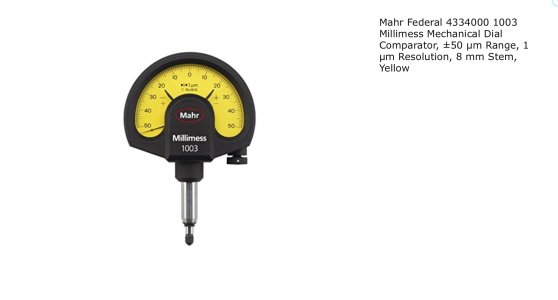
I believe the indicator stand is a FISSO brand and the indicator is a MAHR MILLIMESS.


15BE00F2-E77C-4257-8250-B0A8FE0344BC.jpeg
 
OK so I tried to make my own spring. Found a piece of 1" X 1/8 cold rolled steel and pressed about 1 foot length against my bath room scale to see how much force I would get. I got about 11 pounds a far cry from Gelbarts 100 kilo! Looking through the video comments I see he gives a more complete answer than I had when I first watched it. He says 1" X 1/4" cold rolled about 400 mm long. Looks like I have to find a more appropriate piece of steel!

Easier to make like this:

Two 1/4x1x10" straps
One 1/2x1 x 2" block (or stack)
Two clamping bolts
One tension adjusting bolt

20221112_155956.jpg
 
Last edited:
Dan has certainly access to some seriously expensive machines & good measuring equipment.

I believe the indicator stand is a FISSO brand and the indicator is a MAHR MILLIMESS.


View attachment 27853

I always wondered what that indicator stand was, we had one at my last job with a .0001” interapid on it. The stand had been around for ages and outlived many noga and mitutoyo ones,
 
I believe the indicator stand is a FISSO brand

Do you really think the Fisso is any better than the equivalent Noga? That Noga is pretty damn nice! And it has dual fine adjustments that work extremely well.

The indicator is a beauty.
 
The indicator is a beauty.

I managed to pick up a Russian knockoff quite cheaply a decade ago, It arrived unbroken and all... I have used it in anger a few times, and verified other measurements with some confidence.

[addition] The Fisso brand is very high quality. Much like Noga was 30 years ago. I think Noga has slipped a little bit in the last decade, so I think the race goes to Fisso. I just cannot afford one, so I have Noga stands.
 
I just cannot afford one, so I have Noga stands.

That sounds like an apology. I don't think it's warranted. Even if Noga isn't Fisso, it's still a great product. Certainly top of the line among what I have here. In fact, I'm thinking of getting a second one.
 
Back
Top