• Scam Alert. Members are reminded to NOT send money to buy anything. Don't buy things remote and have it shipped - go get it yourself, pay in person, and take your equipment with you. Scammers have burned people on this forum. Urgency, secrecy, excuses, selling for friend, newish members, FUD, are RED FLAGS. A video conference call is not adequate assurance. Face to face interactions are required. Please report suspicions to the forum admins. Stay Safe - anyone can get scammed.

cross slide indicator assembly v2

PeterT

Ultra Member
Premium Member
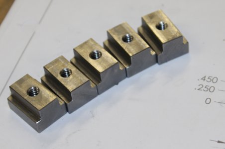
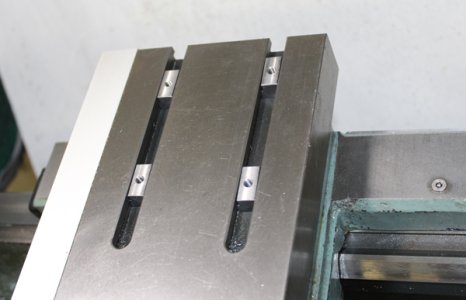
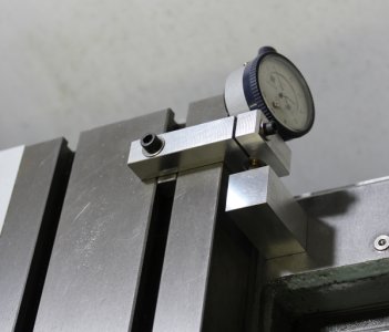
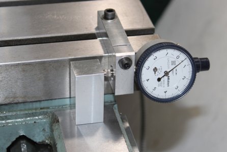
I made some tee nuts for my cross slide for another project. This gave me the idea to make a better, more universal holder for my 0.0001"dial indicator so I can see finer increments than the DRO resolution. I could have extended the holder section a bit more but I tried to keep it compact & rigid, close to the table edge as possible. I can angle the dial at 45-deg which is good enough to see. I can flip the indicator in either direction or add plunger extensions so I think I can reach most any situation. My other clamp was kind of limited & more finicky.

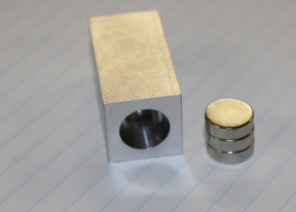
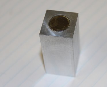
I made a magnetic stop post from aluminum using three 12mm x 4mm neodymium magnets epoxied in a milled hole. It sticks OK but I wish it had more power. Cast iron isn't super magnetic to begin with. I can kind of fit a mag base on there but its a bit clunky. I can make a bar that ties into a plate on the rear of the machine, but the plate is used to hold my DRO encoder so I don't feel like taking it apart unless I'm sure.
 

Attachments

  • IMG_3385_edited-1.jpg
    IMG_3385_edited-1.jpg
    20.7 KB · Views: 15
  • IMG_3389_edited-1.jpg
    IMG_3389_edited-1.jpg
    26.9 KB · Views: 15
  • IMG_3392_edited-1.jpg
    IMG_3392_edited-1.jpg
    14.8 KB · Views: 15
  • IMG_3393_edited-1.jpg
    IMG_3393_edited-1.jpg
    14.1 KB · Views: 15
  • IMG_3395_edited-1.jpg
    IMG_3395_edited-1.jpg
    30.7 KB · Views: 16
  • IMG_3396_edited-1.jpg
    IMG_3396_edited-1.jpg
    32.8 KB · Views: 16
Last edited:
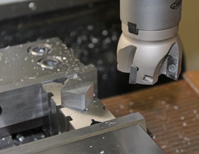
Shop tip I saw on Tom Lipton site. When you have stubby lengths of stock that need to be milled to the exact same length, you can use 2 Vee blocks to trap the corners. That keeps them perfectly in 2 dimensions simultaneously. A parallel resides under the part in between the parallels so once you have the Z dialed in, just whack them down to the same height. I like this better than standing upright in the mill vise with a square. Or extending off the end of the vise jaws because you ideally need support on the other end & some other kind of stop mid way on the vise jaw. Hope this makes sense. The tee nuts & mag block was done this way. I wish I had longer but thinner blocks for this purpose. My little ones will drop through the center slot so I have to keep them on one side resting on the vise bed.
 

Attachments

  • IMG_3391_edited-1.jpg
    IMG_3391_edited-1.jpg
    32.6 KB · Views: 15
Last edited:
Yes, that worked perfectly (PDF upload).

Very nice drawing / part, @PeterT.

You planning to use the TP grinder for super precision work down to tenths?

I wonder if you might have to use the TP itself as the reference surface - it would take care of both cross slide and compound slide deflection / errors.
 
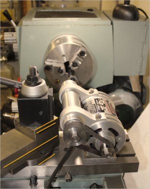
Hi Rudy. Yes, its part of an ongoing (mostly fiddling around) effort to improve the TPG finish & consistency. The current results aren't horrible but I'd like them better. For straight-in grinding, I'm considering mounting the TPG directly on the cross slide over the tee slot area. I figure that might make a more stable foundation & maybe reduce some potential sources of vibration play compared to mounting on the compound slide. When angled grinding is required, no getting around the compound mount of course. But that also means extra mating surfaces are involved: TPG to small footprint adapter plate, adapter plate to compound block via tee nut, compound dovetail sliding surface, compound assembly mounted to cross slide. These surfaces should be considered locked down, but in reality who knows. A little play here & there and all stacked vertically wedding cake mode, maybe adds up?

Re the dial indicator, my DRO reads 0.0005 (diameter) resolution. The dial reads 0.0001 increment, so advancing one visible tick mark = 0.0002 diameter reduction. I'm not expecting that kind of true accuracy because of bigger variables (wheel wear, heat, vibration, spring passes ...) but maybe its a better feedback device of what is truly going on. My other system worked ok but was clumsy. One thing I picked up with my liners is when the TPG is running, the cross slide will float very easily as soon as the dovetail lock is releases due to micro vibrations running through the machine. You can see the indicator needle oscillating back & forth either side of the set position. I think just normal leadscrew backlash allowance will allow that & lets face it, a 90's Taiwan lathe is not a surface grinder. But what I found worked better on final finish passes was turn the motor off, reset Y increment (with dial reading), lock cross slide again, then power on again.

The other mode I considered was canting the compound at a shallow angle & incrementing that in using the angle math for equivalent diameter DOC. But I don't have DRO on that axis & not a good way to mount a dial so 100% dependent on the manual dial reading.

I'm making a few arbors too which are more stout & hopefully less deflection than what I used last time. Its been a bit challenging because Themac has a funky proprietary taper angle in their spindle & I don't have a taper attachment on my lathe. I'll post some more pics as I get closer but anyways, that's kind of what this is about.
 
Shop tip I saw on Tom Lipton site. When you have stubby lengths of stock that need to be milled to the exact same length, you can use 2 Vee blocks to trap the corners. That keeps them perfectly in 2 dimensions simultaneously. A parallel resides under the part in between the parallels so once you have the Z dialed in, just whack them down to the same height. I like this better than standing upright in the mill vise with a square. Or extending off the end of the vise jaws because you ideally need support on the other end & some other kind of stop mid way on the vise jaw. Hope this makes sense. The tee nuts & mag block was done this way. I wish I had longer but thinner blocks for this purpose. My little ones will drop through the center slot so I have to keep them on one side resting on the vise bed.
Well, that's pretty clever.
 
Isn’t is amazing how everything matters when one works below the 1thou range? Great analysis of where your sources of errors are coming from and how to overcome them, Peter.

I remember in the Swissair Technics Jet Engine Overhaul shop they had a CMM that consisted of a 30 metric ton slab of granite that sat on a 2 meter thick concrete base. The measurement times were synchronized to the train schedule - there is a commuter line that runs approximately 200 meters outside the shop (item 2). 5 min before and after a train ran through, there was no valid measurements to be had. They also went to great lengths to acclimatize the turbine blades to the shop’s environment prior to measuring. Even take-offs of heavy jets would influence the readings because of the noise energy transmitted to the building/ground. Oh, there is also the train tunnel underground to the airport terminal (it passes the Technics facility to the west (item 1)) that causes deviation in the readings when a train goes through it.

3AB3C20C-07FE-4925-8FD2-5F41C554A07C.jpeg
 
Isn’t is amazing how everything matters when one works below the 1thou range? Great analysis of where your sources of errors are coming from and how to overcome them, Peter.

I remember in the Swissair Technics Jet Engine Overhaul shop they had a CMM that consisted of a 30 metric ton slab of granite that sat on a 2 meter thick concrete base. The measurement times were synchronized to the train schedule - there is a commuter line that runs approximately 200 meters outside the shop (item 2). 5 min before and after a train ran through, there was no valid measurements to be had. They also went to great lengths to acclimatize the turbine blades to the shop’s environment prior to measuring. Even take-offs of heavy jets would influence the readings because of the noise energy transmitted to the building/ground. Oh, there is also the train tunnel underground to the airport terminal (it passes the Technics facility to the west (item 1)) that causes deviation in the readings when a train goes through it.

That's an interesting story. I recall working in a government facility on 55 AV and Skyline WY NE in the 1990s. The Raytheon facility is out there and the police couldn't use their radar guns anywhere near this place. Raytheon makes the tracking system for the Phalanx Close In Weapons system used on Canadian and US ships. Apparently when they ran tests (in what is now a parking lot behind the building) it messed up instrumentation all around the place.

Things get spooky when interference is accounted for in precision systems, mechanical or electronic.
 
30 tonnes of granite, wow.

Here is roughly what I'm thinking for TPG re-orientation. We'll see if it works. All I am really risking is a bit of plate material as long as I don't shoot my eye out. The orange lines correspond to long winded potential sources of surface contact play. One disadvantage is OD grinding - sparks go up vs. down which is not a good thing. I think I could re-wire internally or better yet a fwd/rev switch. But my principle goal is ID grinding so spin direction doesn't really matter. I don't have a lot of run time / experience on the unit & every combination of material seems to present another permutation of stone & speed & feed. TPGs are bulky so often difficult to get into position & generally don't play well with tail stock support.
 

Attachments

  • 2020-09-21_17-24-23.jpg
    2020-09-21_17-24-23.jpg
    63.3 KB · Views: 14
The granit was about 3x5x0.75 meters. They were measuring fully assembled fan discs on the thing.

Moving the TPG to the slotted part of the cross slide should give you a massive improvement to the rigidity.
 
Back
Top