• Scam Alert. Members are reminded to NOT send money to buy anything. Don't buy things remote and have it shipped - go get it yourself, pay in person, and take your equipment with you. Scammers have burned people on this forum. Urgency, secrecy, excuses, selling for friend, newish members, FUD, are RED FLAGS. A video conference call is not adequate assurance. Face to face interactions are required. Please report suspicions to the forum admins. Stay Safe - anyone can get scammed.

Tips/Techniques Creating a spoil board.

Tips/Techniques

jcdammeyer

John
Premium Member
Creating this and the CAM that went with it was amazingly easy and fast with AlibreCAD/CAM. A friend tried it in Fusion360 and apparently a milled pocket has to have a bottom or it's not a pocket. In AlibreCAM (MecSoftCAM) a pocket has diameter and depth and based on the endmill and rpm the path is circular with a specific depth until the depth is reached. If the depth is larger than the model thickness Fusion360 complains and won't make the pocket.

I whipped up a quick model in Alibre. Easy Peasy. Is it actually easy in Fusion360 and he's just gone down the wrong path?

Side view of the mill path showing a pocket milled deeper than the material.

1731748359026.png
 
Last edited:
I'm not even sure what I'm seeing.

Are those mounting homes for a spoil board? Or is that supposed to be the surfacing operation.

I need to watch me a ton of fusion cam videos, and then learn the limitation work arounds that are on github. Or learn alibre or both
 
That would be easy in Fusion as well. I think maybe he misunderstood the assignment?
Apparently not easy in Fusion.
So here's the basic design.
1. One sketch to create the rectangle 24x36" (or so in metric) extruded up to 19mm (3/4").
2. A second sketch to create an array of 20mm holes that are 40mm apart extrude cut to make holes all the way through.

This took all of a few minutes to create.

1731776405842.png


On the CAM side if one used a milling cutter that was 13mm diameter (or 1/2") it's easy to just use a hole profile process which spirals down cutting away the inside of the hole. But apparently the tool in use is 1/4" (about 6mm) so a hole profile leaves crap in the middle that can fly out or jam.

The better way with that small a cutter is to use the pocket process which cuts a pocket. This time 3mm deep each time with a tool overlap of 25%. the 19mm divided by 3 mm means each hole take 6.333 passes to depth. Or if we want to make sure we go all the way through we make the pocket depth 21mm for 7 passes.

1731777280875.png


Apparently Fusion balks and refuses to create a pocket deeper than the material. I'm not sure why if the drawing shows holes.
 
ah now I see.

I used to make tops like that with a plunge router, a template and a 20mm bit.

now I've ordered a parf guide.

I'm sure that fusion users can create a work around to solve this.
 
Apparently Fusion balks and refuses to create a pocket deeper than the material. I'm not sure why if the drawing shows holes.
Not familiar with this app or the CAM side, but I can also visualize why it would be a flag. Pocket likely means something very specific to the software behind the scenes, so not having a bottom or floor would be a useful diagnostic to know of beforehand even though in your example you can visualize the end result as kind of a workaround. Maybe you need a specific depth for cap screw counterbore but at some later point reduced the material thickness. A hole right through your stock would be an undesirable outcome. Or replace circle with some kind of random internal profile, now the pocket outline, its floor, its top view corner radius & end mill bottom radius & all that other stuff is probably getting vetted behind the scenes. I'm jealous of CAM-ability in the home shop & what you guys are doing. One day maybe....
 
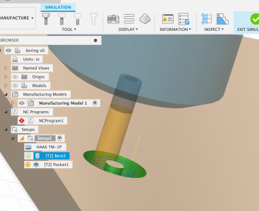
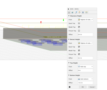
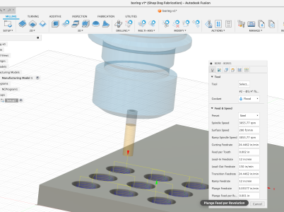
The fusion "Bore" command does let you keep boring through the bottom and beyond, but it does leave an island of stock in the center. For a quick answer in the past I just drilled a large pilot hole first and then ran the bore cycle to get to final diameter. I was trying the pocket command which does let you nicely ramp down and simultaneously step over to the bore diameter. But your friend seems correct that you can't get the pocket command to blow past the bottom of the stock, it just stops at the hole bottom. The pocket is also quite slow - with just the default settings these 9 holes had a 33 minute cycle time. I'm sure you could drill and Bore command faster.

I had no problem setting up pocketing in holes with the 3d pocket command, perhaps the 2d pocket command is more limited.
 

Attachments

  • 1731788479555.png
    1731788479555.png
    469.5 KB · Views: 1
  • 1731786798479.png
    1731786798479.png
    279.7 KB · Views: 1
  • 1731786769202.png
    1731786769202.png
    1.1 MB · Views: 1
Last edited:
I guess it's also a mater of naming convention. When I think of boring on a mill I think of my boring tool and adjust the diameter of the sweep to bore out the hole. And yes, there does need to be an almost the right size hole there or it ends up being multiple boring operations.

The AlibreCAM (MecSoft VisualCAM) differentiates between pocketing any old shape and pocketing a hole. Same with profiling which can be inside a curve or outside a curve. The 3D operations just have radial and spiral machining operations.

1731809717412.png


Using standard pocketing I can also do the hole but it comes out as a series of straight lines and with depth set to 1" on the 3/4" thick material.
1731810213046.png


Now if instead I ask it to use the CAD drawing for depth it doesn't extend below the work.

1731810316250.png


The G-Code is much simpler as it's just straight lines and fairly crude ones. After which once could do a full depth profile operation to smooth the edges.

1731810529096.png


What's sad is the generated G-Code still just uses lines but much shorter as it goes around the hole.

OTOH, then there's a command line program originally written by Jon Elson in C for Linux that I rewrote in Lazarus Object Pascal with a menu entry. IIRC, it has a problem with starting and ending curves that that was also broken in the C language version. But using the IJ directions does make for even shorter G-Code and smooth circles.

1731811070155.png


Code:
( Bore Hole using IJ commands,  G-Code in "P:\lazarus\MakeBore\TestHole3_4.ngc")

N10 G01 F15.0000 X0.00000 Y0.00000

N20 F2.500 Z-0.250

N30 F15.000 X0.03125

N40 G03 X0.00000 Y0.03125 I-0.06250

N50 X-0.06250 Y0.00000 J-0.09375

N60 X0.00000 Y-0.09375 I0.12500

N70 X0.12500 Y0.00000 J0.15625

N80 X0.00000 Y0.15625 I-0.18750

N90 X-0.18750 Y0.00000 J-0.21875

N100 X0.00000 Y-0.21875 I0.25000

N110 X0.20000 Y0.00000 J0.20000

N120 X0.00000 Y0.20000 I-0.20000

N130 X-0.20000 Y0.00000 J-0.20000

N140 X0.00000 Y-0.20000 I0.20000

N150 X0.20000 Y0.00000 J0.20000

N160 G01 F15.0000 X0.00000 Y0.00000

N170 F2.500 Z-0.500
 
Back
Top