• Scam Alert. Members are reminded to NOT send money to buy anything. Don't buy things remote and have it shipped - go get it yourself, pay in person, and take your equipment with you. Scammers have burned people on this forum. Urgency, secrecy, excuses, selling for friend, newish members, FUD, are RED FLAGS. A video conference call is not adequate assurance. Face to face interactions are required. Please report suspicions to the forum admins. Stay Safe - anyone can get scammed.

Colchester Master 2500 DRO installation

TorontoBuilder

Ultra Member
I promised to install the DRO on my brother's lathe within a week or so of his taking possession of the new to him Colchester Master 2500 lathe.

I previously ordered a 2 axis system with linear glass scales with travel lengths of 150mm (5.91") & 1000mm (39.37") for our previous 12x37" lathe and it should fit this new one just fine.

So as I understand things I need to mount the slimline scale to the cross slide, and the read head to the middle of the saddle. Or I may need to install the scale towards the rear of the slide and have the read head on the rear of the saddle.

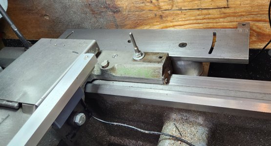
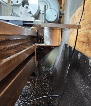
Then I need to mount the other scale to the backside of the lathe bed bellow the flat where the taper attachment normally resides, and the read head mounted to the rear of the saddle on the right hand side closest to the tail stock, where I've scribbled in yellow highlighter. This means installing a a long bracket and perhaps relocating the coolant arm mount.


It all seems simple enough, if I had working arms.

I don't think I'll recover from the effects of moving the lathe for at least 4 days.
 
So as I understand things I need to mount the slimline scale to the cross slide, and the read head to the middle of the saddle. Or I may need to install the scale towards the rear of the slide and have the read head on the rear of the saddle.

I'd suggest embedding the scale inside the cross slide (which is my plan), but I think slim glass won't fit. Unless you are thinking something I don't understand or missed, you only have two choices - right side or left side of cross slide. Either way, I'd put the sensor at the back just to minimize cables flopping around where they can catch on things. That was my thinking anyway.
 
I'd suggest embedding the scale inside the cross slide (which is my plan), but I think slim glass won't fit. Unless you are thinking something I don't understand or missed, you only have two choices - right side or left side of cross slide. Either way, I'd put the sensor at the back just to minimize cables flopping around where they can catch on things. That was my thinking anyway.
Yeah I have seen some installs in the cross slide but I dont think the glass scale will fit. I'd certainly install the reader head at the rear if I can make that work.

I hate trying to plan these things when you don't have access to the machine. 25 minutes is too far away for a shop
 
I mounted my DRO to the carriage on a vertical stalk retaining the swing arm any excess cable is tied to the vertical stalk nothing dragging in the chip pan or pulling on the read heads every thing is fixed to the carriage I also mounted the cross slide scale to the front because of the tail stock
 
I mounted my DRO to the carriage on a vertical stalk retaining the swing arm any excess cable is tied to the vertical stalk nothing dragging in the chip pan or pulling on the read heads every thing is fixed to the carriage I also mounted the cross slide scale to the front because of the tail stock

Need pictures.....
 
Thanks to text messaging I now know more...

The cross slide overhangs the rear of the bed sufficiently to install the rear head on the rear of the carriage along with the read head bracket for the long axis. I will incorporate one or both of these into a new mount for the coolant arm.

-1664600027365936071.jpg


4955668274359189670.jpg
 
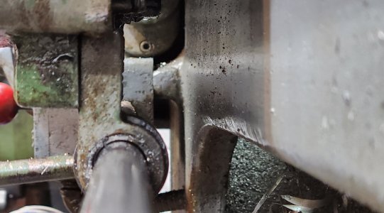
The problem for me is that I have only 24" from the wall to the back of the lathe, and that's if I take the back splash guard off, which is a pain since its made of plwood and has a lot of tools attached. But more importantly, I have my taper turning attachment bolted to the rear rail which would make mounting the reader and scales difficult.

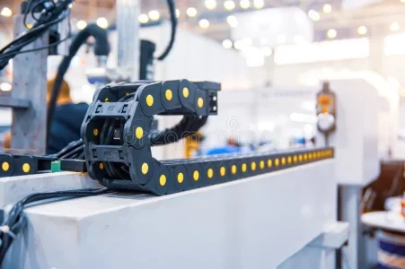
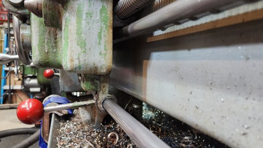
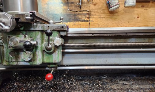
If I mount it on the front, the reader head would be attached to the thick bracket that is on the apron for the start/stop lever, and the scale would be to the right, away from the majority of the swarf. And for cable management use an enclosed cable drag chain somehow.

What thoughts?
 

Attachments

  • plastic-cable-chain-electrical-wires-machine-plastic-cable-chain-electrical-wires-machine-209...webp
    plastic-cable-chain-electrical-wires-machine-plastic-cable-chain-electrical-wires-machine-209...webp
    39.1 KB · Views: 16
  • 20230328_131010.jpg
    20230328_131010.jpg
    236.6 KB · Views: 13
  • 20230328_130848.jpg
    20230328_130848.jpg
    355.2 KB · Views: 12
  • 20230328_130744.jpg
    20230328_130744.jpg
    621.4 KB · Views: 12
  • 20230328_130623.jpg
    20230328_130623.jpg
    418.7 KB · Views: 13
  • 20230328_130459.jpg
    20230328_130459.jpg
    573.5 KB · Views: 15
The problem for me is that I have only 24" from the wall to the back of the lathe, and that's if I take the back splash guard off, which is a pain since its made of plwood and has a lot of tools attached. But more importantly, I have my taper turning attachment bolted to the rear rail which would make mounting the reader and scales difficult.

If I mount it on the front, the reader head would be attached to the thick bracket that is on the apron for the start/stop lever, and the scale would be to the right, away from the majority of the swarf. And for cable management use an enclosed cable drag chain somehow.

What thoughts?

Tom's lathe has 3 rods in the front, an unknown amount of gaps and the larger glass scales to fit. He has plenty of space to the rear of the lathe and no taper turning attachment. He likely won't get a taper attachment either or make one.

I was thinking of getting rocketronics but now I need to check because the lathe as I understand it has rod separate from the lead screw for feeding carriage and cross slide. At this point I don't know enough about either the lathe or the ELS to know for sure what needs doing. So I'm going to err on the side of caution with whatever I do. So I'm leaning to the rear of the bed for now.

To the rear I can have both rear heads close to each other and bundle the wire sets together in a drag chain, and in future add a wire for a rear mounted cross slide servo motor to the same chain drag.
 
@thestelster & @TorontoBuilder

I have the exact same problems and lathe design. That feed rack just under the front Gibb is the biggest issue.

I don't know about mounting a scale behind the start/stop rod.

I fundamentally prefer it out back.

I don't have a taper attachment. Yet anyway...... I routinely consider it though.

Great discussion.
I think I could very likely install the scale on the front, but the cable management would just suck and be far less elegant that could be installed to the rear.
 
I think I could very likely install the scale on the front, but the cable management would just suck and be far less elegant that could be installed to the rear.

I agree. @thestelster s proposed location would work. I know cuz I just looked.

However, I want to put my cross-slide scale inside the cross slide and the only convenient place to put the sensor is behind the cross-slide. That means the sensor cable for it is out back. Since I don't want a mess of cables in my chip tray, I want to integrate the two sensor cables plus the light cable into a single tracked drag chain or single conduit to avoid a huge swarf problem.

So ya, it's going out back. Now that it's made, that decision was obvious.
i did see a post on the scale inside the cross slide... i need to find it and see if that option may work for me... i could order new scales
 
i did see a post on the scale inside the cross slide... i need to find it and see if that option may work for me... i could order new scales

Here you go. @Xyphota blazed that Trail for us.

I've already laid mine out the same way and have about 90% of the design done. Just need to wait for perfect order timing to get the DRO and get it done.

Post in thread 'DRO install on Myford ML7R' https://canadianhobbymetalworkers.com/threads/dro-install-on-myford-ml7r.5963/post-88169
 
Look what I found! I knew someone had done this before, it just took me a while to find their example to copy.

They mounted the scale towards the back of the slide, and the read head on a bracket to the rear of the saddle.

DSC00110.jpg


DSC00115.jpg


DSC00116.jpg


They used too many shim pieces, and I'd like to put 90 degree angle connectors on the read heads, but otherwise this works for me... just need to make and mount a tray with lots of slots to run a chain drag on...
 
Last edited:
Back
Top