• Scam Alert. Members are reminded to NOT send money to buy anything. Don't buy things remote and have it shipped - go get it yourself, pay in person, and take your equipment with you. Scammers have burned people on this forum. Urgency, secrecy, excuses, selling for friend, newish members, FUD, are RED FLAGS. A video conference call is not adequate assurance. Face to face interactions are required. Please report suspicions to the forum admins. Stay Safe - anyone can get scammed.

CNC turned ball

Alexander

Ultra Member
Administrator
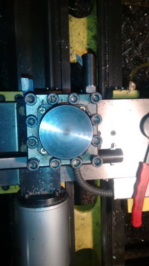
The project is to reproduce some ball joints out of steel. The parts are available at the truck shop but just too expensive. I uploaded the original and the part I made in my little lathe. It was a challenge but a really fun one. One of my buddy's wrote the program and we ran just the first of many today.
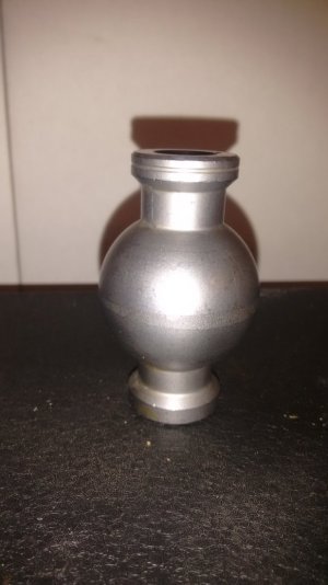
IMG_20151024_160843823.jpg this is the store bought original. Below is what we turned on the CNC.
IMG_20151024_160900236.jpg


Last edited:
No it is a universal joint for racing. Commonly used in 4 link suspension. This is just the inner part of the bal link.
 
lol just thinking my son and I want to build a English wheel and have started getting some metal together. I want to make the anvils myself so I am currently devising plans to have a radius tool that will be ajustable that mounts to the ways. I've made anvils before but thats when I had a Harrison copy lathe.
 
This is the housing for Andrews ball joint. The ID groves are for snaprings so the whole unit will be rebuildable.
IMG_20151031_130243371.jpg
 
IMG_20151031_160328871.jpg I wanted to show off more of the build. Really decent results my lathe needs a bigger spindle motor to actually put a job like this into production.
IMG_20151031_144746561.jpg
IMG_20151031_164638684.jpg
 
This is the last piece to the puzzle. It is half of the bishing that fits around the ball and allows the joint to pivot.
IMG_20151101_114804167.jpg
 
Back
Top