• Scam Alert. Members are reminded to NOT send money to buy anything. Don't buy things remote and have it shipped - go get it yourself, pay in person, and take your equipment with you. Scammers have burned people on this forum. Urgency, secrecy, excuses, selling for friend, newish members, FUD, are RED FLAGS. A video conference call is not adequate assurance. Face to face interactions are required. Please report suspicions to the forum admins. Stay Safe - anyone can get scammed.

Clamp progress

Brian26

Well-Known Member
Premium Member
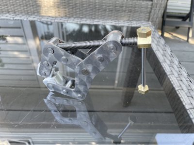
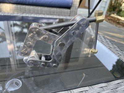
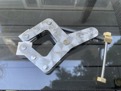
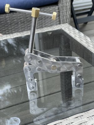
A while back, I bought a kit for two 3" clamps from D.Gray Drafting & Design in Manitoba. I found his method of assembly not for me, mainly because of the complexity of holding everything together with machine bolts. No doubt that is a great way of building for some, and it does offer a degree of dis-assembly - should that ever become necessary. (Looks neat as well!) However, I used his excellent arms to good advantage in putting together the two clamps using the "peened pins" approach that had worked well for me in the past. I have no intention of ever taking these clamps apart, so the peening approach made sense to me. I also added one extra pin to both the short and long arms for added rigidity.

I also made and used some thin bronze washers, and the resulting action on the clamps has to be felt to be fully appreciated. Sooo Smooooth. Since I still have a quantity of those arms I mentioned in a previous post, it is now time to build a pair of 4.5" clamps from my own stock of laser-cut arms. I plan to also add the thin washers (each one is .008") to that build as well. I may get to building a pair of the smallest clamps as well. Those are 2.5" I think - they do not open quite as far as the D. Gray design.

A couple of things to mention... First - my attempt at holding these arms together with super-glue (as recommended) was good in theory - but the final product was out just a little. Second is that that super-glue residue is a real challenge to remove! I did my usual engine-machining to improve the look of the arms but even my carbide-particle pads hardly made any sort of dent in the residue. I tried my best to put these unsightly parts on the inside - but I know they are there...

The next build of the 4.5" clamps will have a change to the pivot pin on which the clamp arms rotate. The D. Gray design features a larger end shaft than my design, so, since it is pretty easy to use a step drill with some accuracy, I plan to open up the 5/16" opening on my arms to accommodate a thicker shaft. The planned 5/16" shaft should be plenty strong enough, but the larger size appeals to me. My thinking is that a step-drill will maintain the accuracy already present due to the laser-cut holes for all axles and pins - so I am hoping for no variance because of this change.

See the attached pictures for some details.
 

Attachments

  • IMG_1092.jpeg
    IMG_1092.jpeg
    321.3 KB · Views: 40
  • IMG_1093.jpeg
    IMG_1093.jpeg
    387.5 KB · Views: 39
  • IMG_1094.jpeg
    IMG_1094.jpeg
    317.2 KB · Views: 39
  • IMG_1097.jpeg
    IMG_1097.jpeg
    426.5 KB · Views: 40
Nice job. Looks great too! Is that 5/16 NC or NF? Would NF offer any benefits?
 
Those clamps are to nice to be used.
How are the pins peened to be able to achieve a smooth action? I used a hammer have not had consistent results, often the joint become to stiff and there is no way back. Do you have a special tool to peen?
 
I use super glue all the time.

Heat will break the bond or soaking in acetone. Acetone works a charm in cleaning the residue up.
Well, heat is how I got them apart. Maybe I used too much glue? I had not realized this glue is so tenacious. Also, there might be differences in the various super glues for sale? Might be worth looking into? I now wonder if a good soaking in Acetone might help get rid of the residue?
 
Those clamps are to nice to be used.
How are the pins peened to be able to achieve a smooth action? I used a hammer have not had consistent results, often the joint become to stiff and there is no way back. Do you have a special tool to peen?
My special tool is a $8 hammer I have had for years. To be clear about this - the peened components do not rotate at all. I am peening just what I am calling the "stand-offs" that both hold the arms apart, but also prevent them from going further apart. The idea is to fix the arms in place using just the peened stand-offs. This is similar to the Kant Twist clamps I got from Amazon, and used as an inspiration for my own design. But, the Amazon clamps are not exactly "peened", but rather the standoffs they use look like they have been pushed together with a lot of force, so their ends are very regular and quite thick.

None of the rotating parts are peened in any way - they just stick through the holes I created using reamers.

Thanks for the question and your kind observation.

In case anyone is curious, my way of peening is to hammer on the end of the standoff piece using my ordinary steel hammer, but I adjust the angle as I hammer around the circumference of the end of the standoff. That way the end gets enlarged more or less evenly as I complete the circle (10 to 12 hammer blows). Then I add a couple of solid blows with the hammer as straight as I can get it, so it hits kind of dead center and shortens the pin ever so slightly. This whole process takes a lot less time to do than to write about it. Needless to say, the opposite side is held against something solid. An anvil would be best, but I have only a rectangle of steel 3" square, and about 5 inches long. You have to do both sides of course.
 
Sounds like you use the flat of the hammer? Why do we have ball peen hammers? I used the ball when peening a post once but I had no idea what I was doing…
 
Today I watched three or four YouTube videos on the subject of peening. Everyone used the rounded end of a ball peen hammer. Must be something to that I surmise. Maybe it has to do with the rounded end being able to pound down the edge without hitting the plates? That's possible for sure. I think that my method provides the clamps with plenty of strength so they should stay together for a very long time, but if even more strength was ever to be needed, I would increase the length of the protruding small diameter - the part that I peen over, and then flatten that some more. If it were a little longer (longer than .030" that is) it would also serve to help avoid striking the arm plates and that might look a bit better.

I wonder if anyone in our group can tell me - and perhaps others, just why we should use the rounded end of a ball peen hammer? I would really like to know. It has always seemed to me that hitting something with the smallest possible part of a hammer was a poor way to deform something made of steel. So, without thinking too much, I just started using the usual business end of a regular hammer. But, if I am missing something, I sure am willing to do things differently.
 
Brian26, After reading your detailed explanation and looking at your picture, I now clearly see how they are put together, Thank you.
You also made me realized multiple angled hits with the hammer around the circumference is the key to achieve a decent peened rivet when done manually. I was trying to peen with a heavy single hammer blow like the automated press machines Duh! My aim with the hammer were never perfect and usually off set to one side, the peened rivets always looked terrible. A hammer is a simple tool but if I paid more attention maybe I could achieved more secured and better looking peened rivets.
 
Today I watched three or four YouTube videos on the subject of peening. Everyone used the rounded end of a ball peen hammer. Must be something to that I surmise. Maybe it has to do with the rounded end being able to pound down the edge without hitting the plates? That's possible for sure. I think that my method provides the clamps with plenty of strength so they should stay together for a very long time, but if even more strength was ever to be needed, I would increase the length of the protruding small diameter - the part that I peen over, and then flatten that some more. If it were a little longer (longer than .030" that is) it would also serve to help avoid striking the arm plates and that might look a bit better.

I wonder if anyone in our group can tell me - and perhaps others, just why we should use the rounded end of a ball peen hammer? I would really like to know. It has always seemed to me that hitting something with the smallest possible part of a hammer was a poor way to deform something made of steel. So, without thinking too much, I just started using the usual business end of a regular hammer. But, if I am missing something, I sure am willing to do things differently.
I would think that the ball end of the hammer serves to concentrate the force of the blow and thus deform the metal to a larger extent . Like using a centerpunch rather than a flat faced punch . More PSI basically .
 
I would think that the ball end of the hammer serves to concentrate the force of the blow and thus deform the metal to a larger extent . Like using a centerpunch rather than a flat faced punch . More PSI basically .

I believe you are exactly right. The force and momentum are the same, but the area is greatly reduced and focussed and the psi goes up. In order to permanently deform the metal, its yield strength must be exceeded into its plastic region. Therefore it is easier to deform the metal if the contact area of the hammer is smaller. Even a small reduction makes a difference.

About 50 years ago I had an aluminium boat that was oil canning when it hit a wave. After corresponding with the manufacturer by snail mail, they shipped me two new structural reinforcement ribs and a box of rivets. I drilled and riveted them in using a BFH and two riveting anvils one inside and one outside. Both had rounded cups in them to form the rivet heads. It wasn't necessary to go around and around because of the cups in the anvil. It also wasn't necessary to be careful about where I hit because the two anvils focussed the force of the blows. The same could be done with Steel, but the anvils would have to be made of significantly harder metal than the pins.
 
Somewhere in my shop is a large cast fixture with special punch for peening rivets on sickle sections. The punch has a cone on the end to form a nice dome on the rivets. Made by JD to aid in repairing mower and swather knives.
 
Yes RobinHood we have one of those as well, they were meant to fix sections while on the machine.
 
I feel like I’m watching tubalcain and his what the heck is this tool episodes. Rudy what is that? I guess I mean how does it work?

Same as what @6.5 Fan described but perhaps a different make.

Uses screw thread leverage to set and form rivets and perhaps remove broken ones too.
 
Ahh yes another one of those things every swather, straight cut combine or hay mower tractor had in the tool box on every farm.

We had two versions (as Susk said)
, both had the H frame in the photo but i dont remember having a spring on the "old rivet punch" as in photo
Janger asked "how do they work;
The one lobe of the tool is simply a punch for removing any rivets that hung up when the knife section came loose. The other lobe is where the action happens. On both versions we had, the large threaded bolt was long enough to reach the opposite side of the H frame. You would use it to pinch the new rivet and the new knife section and the knife bar all tight together so when riveted there was no slack or movement to the new section.
Now this is where our two models differed, one had a simple hole drilled in the center of axis of the tightening bolt for a punch to slide freely inside, in use, after the bolt sucked everything up tight the punch was hit hard with a hammer a couple of times to dome the new rivet shaft. This model worked better with the knife bar out of the machine and on a solid welding bench or anvil in front of the shop....out in the field without a solid base to support it, the riveting was sometimes sub-par and as well the knife bar could be bent between knife guards by the pounding.
The second model was much better in the field, still used the old rivet punch same as the first but the new riveting lobe had no beater punch, it was two threaded bolts, the outside one to tighten everything together same as the first model but it had the second threaded bolt inside instead of the hammer punch that was simply screwed (long wrench or flex handle) down onto the new rivet to set the new dome....no hammer beating or glancing blows to hand or fingers.
 
Thanks for explaining the operation of the de-riveter / riveting tool @historicalarms.

@Janger , there are basically two ways to form a rivet head: with percussive blows (hammer or hammer and punch) or with a “screw former”.

Once the rivet is ”set”, a screw former (domer) uses the friction of the cup shaped, screw driven end to form the rivet head. It does this by mechanically squeezing the rivet and the simultaneous rotation of the domer puts a nice round head onto the rivet.

Exactly as @historicalarms states in his last paragraph, much less chance of injury by glancing hammer blows is the main advantage of the tool.
 
Back
Top