• Scam Alert. Members are reminded to NOT send money to buy anything. Don't buy things remote and have it shipped - go get it yourself, pay in person, and take your equipment with you. Scammers have burned people on this forum. Urgency, secrecy, excuses, selling for friend, newish members, FUD, are RED FLAGS. A video conference call is not adequate assurance. Face to face interactions are required. Please report suspicions to the forum admins. Stay Safe - anyone can get scammed.

Bridgeport Mill Tachometer

Susquatch

Ultra Member
Administrator
Moderator
Premium Member
I am pulling together a control box for my Bridgeport Mills. It is mainly to facilitate VFD controls like a fwrd/rev switch and a frequency Potentiometer. But I have a hankering to be able to see the actual spindle speed.

My best idea to do this so far is a hall effect transducer on the nose. Basically, a small magnet glued to the spindle nose and a hall effect sensor screwed to the nose cap with a wire loop back up to the control box.

I'm not thrilled with this idea though. The wire would have to be guarded, and might be easily broken. I wish there was a better way.

Have any of you done this? Any better ideas?
 
I've been thinking about a tach also. There doesn't seem to be an easy solution for placement of the sensor and magnet without major disassembly of the head. To read actual spindle speed in high and low range the magnet would have to be placed on the bottom of the spindle pulley on a variable speed head as the top of the pulley moves up and down with speed adjustment. I have made the parts to fit the spindle nose as you mentioned but I too would prefer something else.
 
I've been thinking about a tach also. There doesn't seem to be an easy solution for placement of the sensor and magnet without major disassembly of the head. To read actual spindle speed in high and low range the magnet would have to be placed on the bottom of the spindle pulley on a variable speed head as the top of the pulley moves up and down with speed adjustment. I have made the parts to fit the spindle nose as you mentioned but I too would prefer something else.
I'm not sure disassembling the head would help. It's the same problem top to bottom. Maybe a longer draw bar head that always sticks out above the housing?

Let's see what others suggest.
 
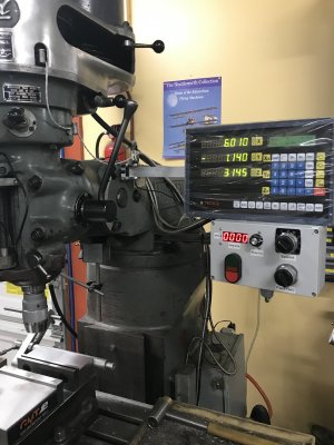
Not a Bridgeport but close enough ...
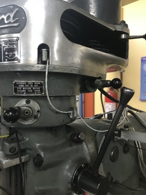
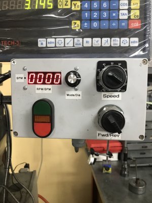
I also installed a VFD control box with a tach on my mill some years ago. After much thought and fiddling around I ended up dismantling the head to install a hall effect sensor and magnet. (The project would have taken less time if I'd just done that in the first place!) It really wasn't too much work or trouble to "do it right".

The tach was a Mach Tach kit that was commercially available a few years ago. The developer is now making the information and files available through Thingiverse.
Anyway ... very happy with the result.

tempImagectHStg.jpgtempImageQFEC7C.jpg
tempImagehSg9O2.jpgtempImagequqc3N.jpg
 
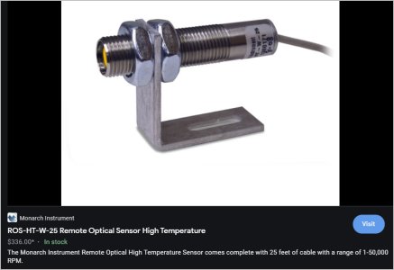
Could you paint a stripe on some inconspicuous area of output shaft & point at it with one of these? I'm thinking somewhere in the belt area out of the way, but maybe there s no direct line of site. I've only used the gun style & they need either a color interruption? Would the sensor care if it was pointed at a white stripe on the black drive belt for example?

https://www.amazon.ca/Digital-Displ...ocphy=9001292&hvtargid=pla-585002351704&psc=1

That's not optical, it relies on a magnet being installed on a shaft or pulley somewhere.
 
Could you paint a stripe on some inconspicuous area of output shaft & point at it with one of these? I'm thinking somewhere in the belt area out of the way, but maybe there s no direct line of site. I've only used the gun style & they need either a color interruption? Would the sensor care if it was pointed at a white stripe on the black drive belt for example?

https://www.amazon.ca/Digital-Displ...ocphy=9001292&hvtargid=pla-585002351704&psc=1


The one in your link is hall effect not optical.

I am using an optical gun right now with a stripe of reflective tape on the spindle nose. It works just fine but optical has its downsides and handheld just sucks. I prefer hall effect because the signal quality is heads and shoulders better than reflective optical.

Regardless, both are essentially the same from a functional standpoint. Nose Mounted, wiring loop required, very messy environment.
 
Not a Bridgeport but close enough ...
I also installed a VFD control box with a tach on my mill some years ago. After much thought and fiddling around I ended up dismantling the head to install a hall effect sensor and magnet. (The project would have taken less time if I'd just done that in the first place!) It really wasn't too much work or trouble to "do it right".

The tach was a Mach Tach kit that was commercially available a few years ago. The developer is now making the information and files available through Thingiverse.
Anyway ... very happy with the result.

View attachment 17360View attachment 17361
View attachment 17362View attachment 17363

I like this. I also like your control box. That's more or less what I want too.

So how does this connect internally inside the mill head?
 
If I remember correctly, I potted a Hall effect sensor into a length of small diameter tubing for positioning and mounting. An angled hole was drilled through the “gearbox” cover alongside the lubrication way to suit the tubing and the whole lot epoxied in place with JB Weld. The (shielded) cable was then routed out the side of the housing as shown. A magnet was epoxied into a shallow depression cut into the top of the large gear near the outer edge to trigger the Hall effect (remember North/south polarity if required for the sensor being used). Using a strong magnet will help ensure enough field to trigger the sensor if the sensor and magnet end up a bit further apart than intended.

Sorry no pictures “under the hood” and i don’t feel up to dismantling it all to take any right now. I have attached one showing the tubing in place.

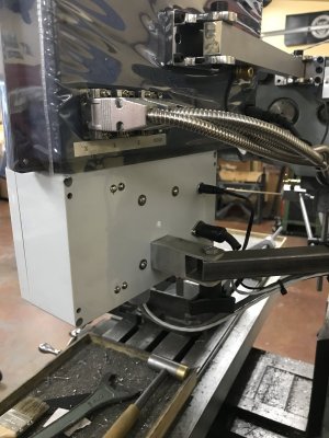
The cable from the Hall effect is terminated in a 3 pin shielded connector that plugs into a matching receptacle on the back of the control box.
54ADDCD0-6F8E-4560-8E2F-16D28BE2BF49.jpeg
 
Your Teco VFD has a scaling parameter that allows you to display the actual speed on the VFD display, once you have calibrated it with your tach. This assumes you won't be changing your belts an modifying your ratios (just a thought)
 
Check this video out for how this guy gets his speed feed from the mill to sync with a servo - I may be making something like this in a while - but it may help you out with a spindle speed that is highly accurate.


The spring loaded diamond etcher is cool as well
 
Arduino, 16x2 LCD, IR transmitter/receiver, paint stripe on quill locknut. Maybe $30 in parts, a couple of hours work. Only snag I had was my shop door has a window that lets outside light shine on the mill. IR receivers don’t like sunshine. I have a Busy Bee CT129 / Grizzly G0704 mill, and I had removed the motor shroud, but had to put it back on to block the outside light hitting the sensor.

I tried the hall effect / magnet system, but the magnet kept picking up swarf.

Let me know if this sounds viable and I‘ll take some photos and dig up the links for the software.

How many volts does it take to drive that? DC I assume? I'm trying to avoid running a power cord from a wall wart.
 
Last edited:
Sorry, I should have read before I clicked. I thought it was a laser style & they have dropped in price, but alas not
 

Attachments

  • SNAG-2021-09-29 7.58.56 PM.jpg
    SNAG-2021-09-29 7.58.56 PM.jpg
    42.4 KB · Views: 5
Your Teco VFD has a scaling parameter that allows you to display the actual speed on the VFD display, once you have calibrated it with your tach. This assumes you won't be changing your belts an modifying your ratios (just a thought)

I didn't notice that my VFD could do that. VERY COOL! Thank you @Dabbler !!! I suppose I could select a standard belt and back gear setup and then program the VFD to match.

I confess that I am still hoping I can at least use the back gear. If I can get a tach to work independent of belt position and back gear, then why not!
 
Check this video out for how this guy gets his speed feed from the mill to sync with a servo - I may be making something like this in a while - but it may help you out with a spindle speed that is highly accurate.


The spring loaded diamond etcher is cool as well

I LOVE THE DIAMOND ETCHER!!!

The Encoder - not so much. That would be a ton of work if it's even possible to get that installed on the spindle someplace. That said, perhaps it's possible to use the bottom clutch teeth as an Encoder albeit with reduced resolution (but plenty good enough for rpm). I'm in there anyway right now trying to get rid of that noise (see Hartford Thread), so I'll look at that idea too. Thanks @Brent H !
 
How many volts does it take to drive that? DC I assume? I'm trying to avoid running a power cord from a wall wart.

Arduino runs on 5 volt DC, or can accept 7 to 12 volt DC if I use the on-board regulator. maybe 50 mA. I run it off a wall wart.

I never thought about it, butI bet I could parasite off the 5 volt supply feeding the glass scales on the DRO.
 
Arduino, 16x2 LCD, IR transmitter/receiver, paint stripe on quill locknut. Maybe $30 in parts, a couple of hours work. Only snag I had was my shop door has a window that lets outside light shine on the mill. IR receivers don’t like sunshine. I have a Busy Bee CT129 / Grizzly G0704 mill, and I had removed the motor shroud, but had to put it back on to block the outside light hitting the sensor.

I tried the hall effect / magnet system, but the magnet kept picking up swarf.

Let me know if this sounds viable and I‘ll take some photos and dig up the links for the software.

Sounds great! I'm not sure how your system picks up a paint stripe though. My Quill nut moves up and down about 6 inches. And most of that is buried inside the mill head.

Yes, I agree that swarf and magnets don't mix very well. Yet another reason to rule out that solution.

If I end up going with an optical sensor system, I'll try to avoid IR.

Boy, you do like Arduino don't you!

If I do end up going that way, I'll get back to you and take you up on your offer.
 
Back
Top