• Scam Alert. Members are reminded to NOT send money to buy anything. Don't buy things remote and have it shipped - go get it yourself, pay in person, and take your equipment with you. Scammers have burned people on this forum. Urgency, secrecy, excuses, selling for friend, newish members, FUD, are RED FLAGS. A video conference call is not adequate assurance. Face to face interactions are required. Please report suspicions to the forum admins. Stay Safe - anyone can get scammed.

Any change gear gurus on here.

Desab

Member
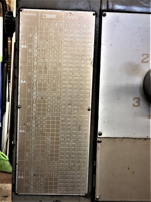
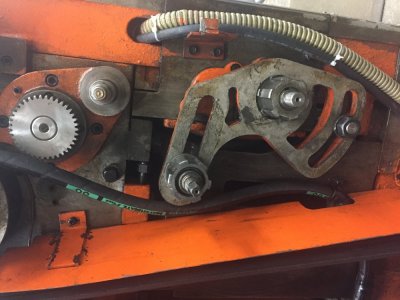
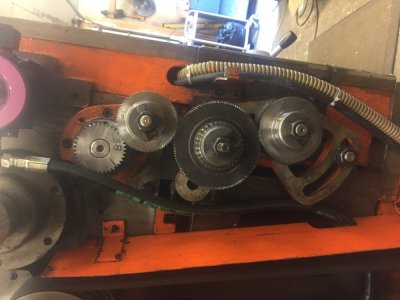
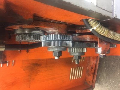
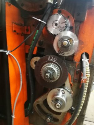
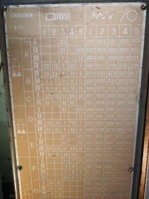
Attached pic of my gear train, I can only cut threads section F 36 thru 3,
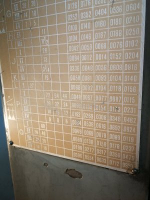
i have zero info for this lathe, my quest is to cut proper change gears for threads and feed listed, doesn't seem to have a lot of options.
it appears as there are 2 spots for extra gears
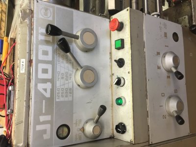
"oops all the pic are rotatedView attachment 13206
 

Attachments

  • IMG_1878 (3).JPG
    IMG_1878 (3).JPG
    145.3 KB · Views: 34
  • IMG_1277.JPG
    IMG_1277.JPG
    108.2 KB · Views: 35
  • IMG_1848.JPG
    IMG_1848.JPG
    128.2 KB · Views: 31
  • IMG_1849.JPG
    IMG_1849.JPG
    127.3 KB · Views: 26
  • IMG_1850.JPG
    IMG_1850.JPG
    113.2 KB · Views: 28
  • IMG_1851.JPG
    IMG_1851.JPG
    97.7 KB · Views: 27
Last edited:
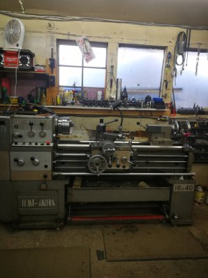
Post a few images of the entire lathe. Maybe some one will recognize what it is and where it was made. Then you can search for a manual.
 
To properly calculate the gear ratios of your QCGB the current installed gears by tooth count, the TPI of the lead screw. Without all of those things, guessing the correct change gears is impossible.

The contrast is so bad for the gear chart I can't read the necessary gear settings, either.

Even then you can eliminate a lot of the work by fully documenting the QCGB. then it is an easy spreadsheet to calculate everything and get you a proper change gear diagram with its effects on all the gears.
 
Face plate states the lead screw is 4 TPI, the rest I can't read.
 
Last edited:
As installed in the last picture, your ratios are 38:30 -> 80:120:90 which gives .63333 turns of your QCGB per turn of the spindle.

That gives effective QCGB gear ratios as follows (for the letter F):

I3 - .1754 I4 - .1973 I5 - .2631,
II3 - .3509 II4 - .3947 II5 - .5263
III3 - .7018 III4 - .7895 II5 - 1.503
IV3 - 1.404 IV4- 1/579 IV5 - 2.105

and so on, but I would have to guess at the gear combinations that made up your QCGB ratios.

We also have no information about the ratios provided by the 1 and 2 positions, as well as all the other letters. Now I could begin to assemble a 'best guess' as to the required ratios for the backtracked lead screw values but that would be a bunch more hours of work.

If I were to be ordering the missing gears, I'd first open the QCGB and document the gear train.

You will have to carefully document the modulus of the change gears and the pressure angle. Note that you have two completely different systems of gearing, a coarse modulus on the 38/30 gears and a fine modulus for the rest.

You obtain the modulus by measuring the "reference diameter" which is the circumference of the circle that the gear describes, and dividing it by the number of teeth. I hope that you don't have mixed ISO and Metric modulus, that will make things a little more complicated.

This is why it is easier to find the manufacturer and order the gears directly from them, or find a manual and look up the required gears. I have attached a complete description of gear module
 

Attachments

Last edited:
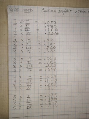
Im not sure if this will help, I measured QCGB per 1 revolution the carriage moves as per my list attached.
the fine gears are module 1
BTW I have tried and still trying to locate a manual, the manufacturer is Jinan First Machine Tool I have email them several times but no reply.
thanks
 

Attachments

  • list (2).jpg
    list (2).jpg
    92.4 KB · Views: 11
Last edited:
If you google Jinan First Machine Tool they come up. Perhaps patience here is key. (or a phone call??)
 
it appears as there are 2 spots for extra gears

Sorry, what do you mean by that?

From the posted pictures, you have 4 places total where you can put gears. I labelled them for you 1-4.

1F2711B2-4560-4513-BD42-B8E7F470DEBE.jpeg


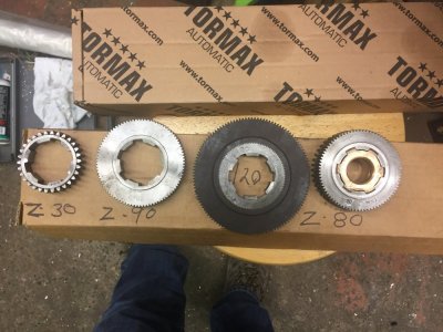
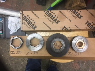
The best way for us to help you is if you take a black sharpe and write the # teeth right onto each gear in big numbers, install them and then take a picture.

Position 1 is the input. Right now it has a 38T gear on it. It meshes with the 30T gear (I believe it is hidden behind the 80T (maybe 90T - can’t really tell) gear in the other picture. Can you please confirm, thanks. If you put gears with different teeth count onto the same shaft and they are splined together, you have made a compound gear, whose ratio must be considered in calculating a gear train (together with the input gear and the output gear). Everything else is just a filler (position 2 & 3 - unless they are compounded) and can be disregarded. You probably already know that.
Position 4 is the output of the gear train (input shaft of the QCGB).

So, can you also show us a side view of you gear train (a sketch will suffice) like in this example:

2CEFE6E6-C7D8-4F52-B0D2-A013D89C418B.jpeg


In your case, I don’t expect to see a single row of gears as you have a compound set-up.

Where am I going with this? You may not be missing as many gears as you think you are. I am pretty sure that you need a 127T gear for your metric and module threads. It would take the place of the 120T gear you have in a compound set-up.

Question: have you actually threaded the pitches in the “F” portion of the table and measured them for accuracy? And what was your gear train set-up for that? The one you took a picture of?

FDB9E632-00AC-4386-A696-65770AA6566E.jpeg


If the gear train is set-up properly (with the gears you have), you will get the accurate threads and the same feeds (inches/spindle rev) as the chart on your lathe under section “F” shows. From your actual feeds chart you posted above, you are not matching what the lathe says you are supposed to get. The gear train and / or QCGB is most likely not set correctly.
 
new info on gear change.
top 38 meshes with 46 tooth behind 80 which meshes with 120 to 90
the gear in front of the 120 which is a 30 tooth coarse does not mesh with 38 or 46
Gears Z80,Z90,Z120 are Module 1. Gears 38 and 46 are unknown (i don't think they are metric)
the single gear 30 i believe is metric but module unknown

also all the feeds in section F all corresponds with the table,

the list that i posted in the earlier post was with the gear train disengaged that's why it doesn't correspond
with the feed table.
Presently working on a 127 tooth gear.

Hopefully i am making some sense.
 

Attachments

  • IMG_20210210_141318.jpg
    IMG_20210210_141318.jpg
    94.1 KB · Views: 14
  • IMG_20210209_125835.jpg
    IMG_20210209_125835.jpg
    114.6 KB · Views: 14
  • IMG_20210209_124608.jpg
    IMG_20210209_124608.jpg
    99.5 KB · Views: 13
  • IMG_20210209_124229.jpg
    IMG_20210209_124229.jpg
    132.2 KB · Views: 5
Back
Top