• Scam Alert. Members are reminded to NOT send money to buy anything. Don't buy things remote and have it shipped - go get it yourself, pay in person, and take your equipment with you. Scammers have burned people on this forum. Urgency, secrecy, excuses, selling for friend, newish members, FUD, are RED FLAGS. A video conference call is not adequate assurance. Face to face interactions are required. Please report suspicions to the forum admins. Stay Safe - anyone can get scammed.

Tips/Techniques Another way to make a surface grinder balancing ring

Tips/Techniques

Susquatch

Ultra Member
Administrator
Moderator
Premium Member
I thoroughly enjoyed following @thestelster 's thread where he made 4 really cool balancing rings for his surface grinder.

Thread 'Surface Grinder Adapter Balancing Rings' https://canadianhobbymetalworkers.com/threads/surface-grinder-adapter-balancing-rings.8952/

But as I commented on his post, I don't have any flat lock like he did. Instead I have round bar the right size. That dictated a different approach to the job. So I thought I would share what I did and how I did it......

First off is the round bar. It had been used in a previous project.

20231029_112654.jpg


Next up was mounting it in the 3-jaw. I was gunna cut enough off that truing it up in a 4jaw was not necessary. It would get trued automatically as it got turned. First I drilled it out to about 1 inch. Then I switched to a boring bar and bored it out till it fit the grinding wheel arbour.

20231028_155457.jpg


Here it is finished boring to fit the arbour.

20231028_160105.jpg


As @thestelster noted, cutting the inside radius was a bit finicky. But I have a handground chamfer form tool that I can use to fine tune to fit. This photo shows the chamfer and starting to cut the OD.

20231028_162219.jpg
 
I deliberately sized the work to make 2 balancing rings. I have 4 arbours and 2 are a slightly different size from the other two. So I decided to just make two at a time. I would also like to try using steel epoxy to balance a wheel, so again it made sense to just make two.

I parted them off one at a time using this tool. I guess I forgot to take a photo while I was parting. Each ring is 3/8 thick so it was just a matter of setting the parting tool to cut off a 3/8 ring, then rechamfer the next ring, rinse and repeat.

20231030_150815.jpg


Here are the two rings, and the arbour they go on. I also made a sleeve out of 2" ABS Pipe at the same time.

20231029_105858.jpg


The purpose of the ABS Sleeve is to hold the rings high enough above my rotary table so I don't end up drilling or tapping into the table. The ABS sleeve is sized to be a press fit to the ring with an inside shoulder that the ring sits on.

20231029_105930.jpg
 
Next up is mounting the rings on my rotary table for drilling and tapping.

There are lots of ways to do this, but I like collets and sleeves. I put an MT3 endmill holder into the MT3 center of my table. Then, I made a sleeve out of black pipe that was sized to fit the OD of the end mill holder and the ID of the ring. This ensures that the ring is centered on the axis of rotation of the table. I could have also used an indicator to dial the ring in, but..... I like sleeves and collets! LOL!!!

20231102_140035.jpg


Note that this is a 10" Rotary Table. Look how full it got just holding a little ring. The purpose of the ABS sleeve and the black pipe sleeve should be a little more obvious now.

Here we are drilling holes. I deliberately departed from the normal 16 holes and did 18 instead. By choosing 18 holes instead of 16, the interval is 20 degrees. Easy peasy to do using the regular degree marks and their corresponding Vernier scale.

20231102_144221.jpg


It worked out great with lots of room between holes. I drilled using a 5.3mm drill so I could get a 65% thread fit which is ideal for threading in Aluminium with low probability of breaking a tap and plenty of thread strength. That was important because I planned to power tap like @thestelster did. I believe that everyone has to learn something new every day of their lives. This was my day to learn to power thread for the very first time.

However, I don't have resistive braking in my mill yet which is another reason for the tall ABS sleeve. That meant that power tapping might be a bit touchy. I turned down the speed, kept my hand on the reverse switch, and dove in...... NICE!

20231102_152501.jpg


34 holes spotted, drilled, and then power tapped, and I was done. I did the two holding set screws the normal way in my vise, and then lightly chamfered everything.

All done. Here are all the parts.

20231102_184059.jpg

Very happy.

I'll try balancing a wheel in the near future.

As stated above, I also plan to try it using steel filled epoxy.
 
While I'm skeptical about the speed of this structural adjustment balance, I'm still excited about what I've seen SUS make, please go ahead and make more!
 
Next up is mounting the rings on my rotary table for drilling and tapping.

There are lots of ways to do this, but I like collets and sleeves. I put an MT3 endmill holder into the MT3 center of my table. Then, I made a sleeve out of black pipe that was sized to fit the OD of the end mill holder and the ID of the ring. This ensures that the ring is centered on the axis of rotation of the table. I could have also used an indicator to dial the ring in, but..... I like sleeves and collets! LOL!!!

View attachment 39632

Note that this is a 10" Rotary Table. Look how full it got just holding a little ring. The purpose of the ABS sleeve and the black pipe sleeve should be a little more obvious now.

Here we are drilling holes. I deliberately departed from the normal 16 holes and did 18 instead. By choosing 18 holes instead of 16, the interval is 20 degrees. Easy peasy to do using the regular degree marks and their corresponding Vernier scale.

View attachment 39637

It worked out great with lots of room between holes. I drilled using a 5.3mm drill so I could get a 65% thread fit which is ideal for threading in Aluminium with low probability of breaking a tap and plenty of thread strength. That was important because I planned to power tap like @thestelster did. I believe that everyone has to learn something new every day of their lives. This was my day to learn to power thread for the very first time.

However, I don't have resistive braking in my mill yet which is another reason for the tall ABS sleeve. That meant that power tapping might be a bit touchy. I turned down the speed, kept my hand on the reverse switch, and dove in...... NICE!

View attachment 39638

34 holes spotted, drilled, and then power tapped, and I was done. I did the two holding set screws the normal way in my vise, and then lightly chamfered everything.

All done. Here are all the parts.

View attachment 39639
Very happy.

I'll try balancing a wheel in the near future.

As stated above, I also plan to try it using steel filled epoxy.
Why not use chuck to drill holes? Are you worried about the height of the Z-axis?
 
Nice

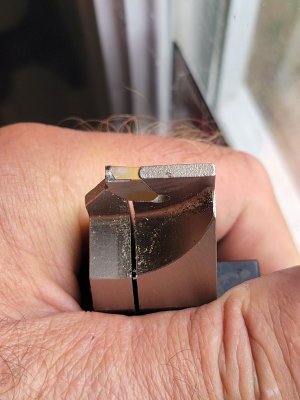
Is it my eyes or is your parting insert chipped?

Aluminium Deposits I think. The bit is for steel, so the edge has multiple curves in it. I did have to stop on one of the cuts to remove a roll that stuck to the insert and stopped the cut. But I'll take a closer look later today. Chips in expensive carbide bits is one reason I don't hate HSS.

Ironically, the aluminum bits I ordered a month ago arrived last night - AFTER I finished the job! As you might expect, being for aluminium, they are sharp and square. Next time.
 
Why not use chuck to drill holes? Are you worried about the height of the Z-axis?

Two reasons:

1. I am very tall. Lowering the bed to accommodate a drill chuck works against that. So I hate drill chucks.

2. This was my very first shot at power tapping. My chuck is keyless. I've heard horror stories about backing out a tap in reverse with a keyless chuck. Someday I will get a nice keyed chuck with ball bearings.


That said, I thought about it long and hard. With a chuck, I could have changed the bits without changing collets. As it is, I had to set zero on my DRO so I could move the table out of the way to get the room to change collets and bits without losing the alignment.
 
While I'm skeptical about the speed of this structural adjustment balance,

Skepticism is always healthy. Please explain what bothers you so we can fuss about it together! It will be fun! I'm pretty sure @thestelster, and a dozen others, would be happy to add their thoughts too.
 
Skepticism is always healthy. Please explain what bothers you so we can fuss about it together! It will be fun! I'm pretty sure @thestelster, and a dozen others, would be happy to add their thoughts too.
My understanding is that screws need to be added to the 17 threaded holes. How do I know how much weight of screws to use in the hole?

I think the difficulty of adjusting the balance is that there are only 17 position points and you need to use different weights of screws. Therefore, it is difficult to quickly adjust the balance of the grinding wheel. In other words: It is very difficult to adjust the static balance very accurately!

Maybe there is something wrong with my understanding of the use method. I think the sliding steel ball is more convenient to use. I will make a steel ball version of the flange for test in the near future.

I can't wait to see the video of Daddy SUS's balance!
 
I thoroughly enjoyed following @thestelster 's thread where he made 4 really cool balancing rings for his surface grinder.

Thread 'Surface Grinder Adapter Balancing Rings' https://canadianhobbymetalworkers.com/threads/surface-grinder-adapter-balancing-rings.8952/

But as I commented on his post, I don't have any flat lock like he did. Instead I have round bar the right size. That dictated a different approach to the job. So I thought I would share what I did and how I did it......

First off is the round bar. It had been used in a previous project.

View attachment 39623

Next up was mounting it in the 3-jaw. I was gunna cut enough off that truing it up in a 4jaw was not necessary. It would get trued automatically as it got turned. First I drilled it out to about 1 inch. Then I switched to a boring bar and bored it out till it fit the grinding wheel arbour.

View attachment 39624

Here it is finished boring to fit the arbour.

View attachment 39625

As @thestelster noted, cutting the inside radius was a bit finicky. But I have a handground chamfer form tool that I can use to fine tune to fit. This photo shows the chamfer and starting to cut the OD.

View attachment 39627
Nicely done! I need to do this project as well and was wondering why not put all 18 holes on the outer diameter? Any downside to that?
 
Nicely done! I need to do this project as well and was wondering why not put all 18 holes on the outer diameter? Any downside to that?
I would say, easier access to the set screws when balancing; quick visual inspection of where the set screws are on the ring; (for me), a lot easier to index, drill& tap on the flat side, versus its perimeter.
 
Nicely done! I need to do this project as well and was wondering why not put all 18 holes on the outer diameter? Any downside to that?

What @thestelster said! Plus it looks really cool and less chance of throwing a screw across the room. (Note I said Less chance, not zero). Once balanced, I'll prolly add blue loctite.

Might add a lead ball in front of the radial screw. Not sure of that one. TBD.....
 
My understanding is that screws need to be added to the 17 threaded holes. How do I know how much weight of screws to use in the hole?

I think the difficulty of adjusting the balance is that there are only 17 position points and you need to use different weights of screws. Therefore, it is difficult to quickly adjust the balance of the grinding wheel. In other words: It is very difficult to adjust the static balance very accurately!

Maybe there is something wrong with my understanding of the use method. I think the sliding steel ball is more convenient to use. I will make a steel ball version of the flange for test in the near future.

I can't wait to see the video of Daddy SUS's balance!

I see. You might be right. Time will tell.

My understanding, which could be all wrong, is that only 2 or 3 screws will be needed. Fine tune can be done by walking double screws toward the light point. Also, as you point out, one can use 5/8, 1/2, 3/8, 1/4, 3/16, 1/8 screws. I plan to limit mine to 1/8 through 3/8 so they don't end up proud of the surface.

Video might be a while. Might also be just photos. Videos are a pain in the butt.
 
Is it my eyes or is your parting insert chipped?

Here are some close ups.

20231103_141429.jpg


20231103_141332.jpg


But.........


You are absolutely right!

20231103_141302.jpg


I am learning not to like Carbide. They are constantly breaking on me.

I can't even see a broken edge when I'm staring at it. My eyes have divorced me.

I might have to hire you to keep an eye on my inserts for me......

Great catch Peter! I would never have known till it blew up on me!
 

Attachments

  • 20231103_141302.jpg
    20231103_141302.jpg
    206.3 KB · Views: 5
Back
Top