• Scam Alert. Members are reminded to NOT send money to buy anything. Don't buy things remote and have it shipped - go get it yourself, pay in person, and take your equipment with you. Scammers have burned people on this forum. Urgency, secrecy, excuses, selling for friend, newish members, FUD, are RED FLAGS. A video conference call is not adequate assurance. Face to face interactions are required. Please report suspicions to the forum admins. Stay Safe - anyone can get scammed.

Machine Always to meet new challenges - my first hydraulic press

Machine

a smile

Lifelong hobby - cold iron
Recently, I am busy and have little time to take a walk in the forum.

When I have difficulties in the processing of hexagonal or other polygons with inner holes, I think I can try hot stamping. So purchased a car maintenance side of the hydraulic press rack. Nominal 100T, I will not calculate, but I will check the relevant information. Here are some pictures
The chain crane installed earlier allowed me to unload heavy loads easily.
2023_11_04_10_24_IMG_3800.JPG
2023_11_04_10_15_IMG_3796.JPG
2023_11_04_11_39_IMG_3804.JPG
2023_11_04_11_59_IMG_3824.JPG
2023_11_04_11_54_IMG_3813.JPG

Received it an hour ago today. Can't wait to press the pipe.
 
Is this white part made of aluminum? Below and in the middle is the point of failure.
QQ图片20231104191908.jpg

The hydraulic station purchased a few years ago tried to start today, but there was a small hole leaking oil. What is this part and what is its main role? Filter? Or limit voltage insurance? Is it OK to weld the plug, or to make the thread, is it OK to use the screw plug?
 
That looks like a Fram oil filter, usually on the suction feeding into the pump. Low pressure, anything could be used to repair the hole.
 
As I progressed, I found more questions:
2023_11_04_11_59_IMG_3825.JPG
IMG_3843.JPG
IMG_3847.JPG

Solenoid valve electromagnet core can not move, probably because after a long time to stop the use of a little stuck, I can only open and clean up, now the valve body is also easy to use.

Another major problem was that the hydraulic cylinder began to leak oil after starting, and the oil leak point came from the hollow inside of the hydraulic push rod, and the specific leak point could not be observed. The final decision was to return the product to the seller and replace a 150T pressure hydraulic press frame.
IMG_3859.JPG


I hope there are professional hydraulic practitioners here to answer some of my questions: the piston diameter of this hydraulic cylinder is 140mm, and the design input pressure is 50MPA, which is calculated according to my understanding: 7*7*3.14=153.86*500bar=76930/1000=76T. But the nominal pressure of this hydraulic cylinder is: 100T,
QQ截图20231105130523.webp

Is this my miscalculation? Or the calculation method is wrong? Or is this a nominal error?
 
I think in imperial, so I’ll do the math in imperial.

140mm = 5.5”. Piston area is 5.5”x5.5”x0.7854 = 23.75 square inches. So at 2000 psig, the cylinder develops 23.75 tons of force. At 500 bar 7350 psig, force would be 87 tons.
 
So can anyone tell me what a pascal is?? How does this relate to mm./cm.
Atmosphere - 14.7psi I get.
 
1 bar is 100,000 pascal is 14.7 psig is 401 inch of water column.

I do lots of piping work, easy one to remember is 150 psig is 1050 kilopascal
 
1 bar is 100,000 pascal is 14.7 psig is 401 inch of water column.

I do lots of piping work, easy one to remember is 150 psig is 1050 kilopascal
I do not know much about the imperial system, but according to the accepted pressure is cost-effective: 1 mpa=10.1971621 kg/cm². Calculate the cylinder diameter of 140mm in my picture, and the calculation result is as follows: 7cm*7*3.14=153.86cm² (cylinder area) *50MPA*10197=78445kg/cm=78.445T.

There is still some gap between this and your calculation. I am not sure where the problem lies, but what I can confirm is that the seller's mark is wrong. I hope to get a more accurate calculation, because I will be experimenting with hydraulic devices in the near future. Thank you for your time!
 
I received a new hydraulic press yesterday, this one is bigger than the one leaking oil, the nominal pressure is 150T, but I calculate that this is a 100T hydraulic press, well, this is China - this is China, the country of running without rules!

I installed and tested it in the first place. And as soon as possible to make a relatively simple electric control box, and try to hot press a hex. The correct shape can be formed, which proves that my thinking is correct.


2023_11_06_17_13_IMG_3944.JPG
2023_11_06_19_53_IMG_3945.JPG
2023_11_07_10_39_IMG_3974.jpg
2023_11_07_10_49_IMG_3976.jpg


And start making the clamping jig of the hydraulic press today!
2023_11_08_07_11_IMG_3988.JPG
2023_11_08_07_25_IMG_3992.JPG
2023_11_08_11_17_IMG_3995.JPG
2023_11_08_11_20_IMG_4003.JPG
2023_11_08_12_18_IMG_4016.JPG
2023_11_08_12_21_IMG_4021.JPG
 
I received a new hydraulic press yesterday, this one is bigger than the one leaking oil, the nominal pressure is 150T, but I calculate that this is a 100T hydraulic press...

From your description, I am not sure that you know you can install an oil pressure gauge and then calculate the press force from that using the cross sectional area of the cylinder ram.

I've even seen big units like that with the scale on the pressure gauge directly reading pounds of force.

You could do the same by surrounding the gauge with a second scale.
Because I am unfamiliar with the hydraulic press, I can only rely on the Internet to understand some relevant knowledge, for the time being, I can confirm that: A. The maximum pressure setting value of the hydraulic pump is 200BAR, and it is uncertain whether it can be further increased. I will check some information to make sure that it is safe and then try to increase the pressure. Because the hydraulic nameplate is missing. B. Now the actual pressure value I use is 40T, which is enough according to the test results. C. I still need to improve the control circuit. D. I need to add a pressure sensing controller to control the start and stop of the hydraulic motor. E. I need two of them to be used in parallel to increase the hydraulic flow to meet the speed defect of the cylinder.


Spend an afternoon making some mounting vehicles for hydraulic punch needles and making a punch needle. Without the support of experience, I can only measure while ideating while processing, and can only wait for practice to verify whether my method is correct. The work of the lathe is the main force.
2023_11_08_07_11_IMG_3991.JPG
2023_11_08_11_18_IMG_3998.JPG
2023_11_08_12_21_IMG_4017.JPG
2023_11_08_17_52_IMG_4058.JPG
2023_11_08_18_55_IMG_4084.JPG
2023_11_08_19_08_IMG_4086.JPG
2023_11_08_19_09_IMG_4090.JPG
2023_11_08_19_09_IMG_4091.JPG
 
Because I am unfamiliar with the hydraulic press, I can only rely on the Internet to understand some relevant knowledge, for the time being, I can confirm that: A. The maximum pressure setting value of the hydraulic pump is 200BAR, and it is uncertain whether it can be further increased.

A simple example might help.

200 BAR is just shy of 3000 psi. 3000 psi is a typical max pressure for most high quality85 hydraulic components (hoses fittings, etc) but there is also a lower pressure standard so you do need to be careful.

At 3000 psi with what looks like a 6 inch diameter (3 inch radius) ram, your force is pie R squared times P = 3.14 * 9 * 3000 = 85,000 pounds of force.

Increasing the pressure beyond 3000 psi would be unwise.

Regardless, 85000 is a LOT!

I think you already knew all that. Just making sure. But my real point was to add a pressure gauge and then add a secondary scale to the gauge such that 3000 = 85, 1500 = 42 etc etc.
 
I used DECKEL to drill holes and make some flanges by dividing the circumference 6 equally.
2023_11_09_11_03_IMG_4099.JPG
2023_11_09_11_06_IMG_4106.JPG
2023_11_09_11_34_IMG_4110.JPG
2023_11_09_12_22_IMG_4115.JPG
2023_11_09_15_30_IMG_4130.JPG
2023_11_09_15_30_IMG_4134.JPG
2023_11_09_17_22_IMG_4138.JPG

Tap and chamfer on the flange.
2023_11_09_18_10_IMG_4146.JPG

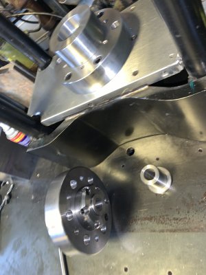
Drill holes and taper wires on the push rod of the hydraulic press. Then install the finished flange, and use it to install the stamping assembly, as well as the mold!
2023_11_09_18_10_IMG_4143.JPG
 
I used DECKEL to drill holes and make some flanges by dividing the circumference 6 equally.
View attachment 40049View attachment 40050View attachment 40051View attachment 40052View attachment 40053View attachment 40054View attachment 40055
Tap and chamfer on the flange.
View attachment 40056
Drill holes and taper wires on the push rod of the hydraulic press. Then install the finished flange, and use it to install the stamping assembly, as well as the mold!
View attachment 40057
You do fine work sir!
 
Some steel plates were purchased and a steel plate plane was planned to be welded on the hydraulic support work surface.
2023_11_10_14_11_IMG_4148.JPG
2023_11_10_15_07_IMG_4155.JPG

A steel plate with a beveled side that needs to be cut off
2023_11_10_14_16_IMG_4149.JPG


It takes more than an hour to dig a hole in the center of the iron plate, 100.00mm in diameter
QQ浏览器截图20231111194130.webp

Use the Angle grinding mechanism to make 4 semi-circular holes
2023_11_10_17_15_IMG_4176.JPG

Flat to the face, I want the hole to be completely concentric with the cylinder. Unfortunately, it was difficult to do, and I had to make another auxiliary shaft to assist the concentric work, which took a lot of time, which made me wonder if the time I spent on this device was worth it.
2023_11_11_10_12_IMG_4191.JPG

2023_11_11_17_09_IMG_4205.JPG
2023_11_11_17_14_IMG_4208.JPG
 
Find a piece of round steel, 182mm in diameter, and start making a flange base.

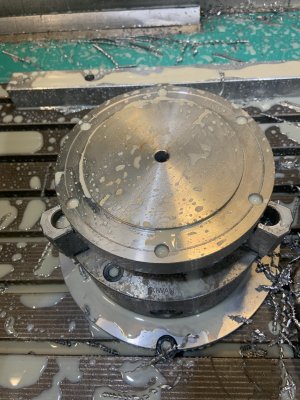
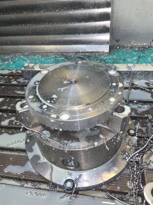
Lathe machining cylindrical, flat. Then use 3-axis CNC punching, this time learning G102, equal round punching. Follow the instructions to program, and then test on air. After confirming that there is no problem, use the tool to process. Finally complete the index hole.
IMG_4604.jpeg
IMG_4617.jpeg
IMG_4610.jpeg

What I want to explain is: I have no time to systematically learn CNC programming. Learn the most basic programming only when you need it. Now have learned to use pecking holes, equal circle, and then will learn Sw-CAM, can be more convenient CNC programming tool path.
 

Attachments

  • IMG_4618.jpeg
    IMG_4618.jpeg
    491.6 KB · Views: 3
  • IMG_4624.jpeg
    IMG_4624.jpeg
    464 KB · Views: 3
Last edited:
Back
Top