This machine "jumped" on my trailer a while back

It has external hydraulics (large tank) and coolant (small tank). In front is a de-mag that came with it.
Coolant and hydraulic motors did not run; here is why (hyd motor shown):

The bearing was full of shmoo. Luckily I don't think they ever ran them like that; it would have spun the bearings - but they were not. Replaced them and cleaned the inside; now they run like a top.
Here was the reason for a spindle vibration I got:

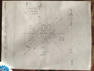
This is the "CJ" style urethane spider from the love-joy type coupling between the spindle and its drive motor. I have already glued the broken off ears back on (you can just see the one @ about 10'o-clock position). The spider is an odd-ball size, of course, and not available off the shelf.... Hence the drawing and the home made cutter.
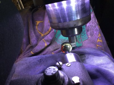
Here is the cutter in use:

I made Delrin spiders first to see if my geometry was correct before I attempted it in rubber...

If rubber does not last, I now have an accurate part that I can make a mold from and cast a spider out of liquid urethane, if required.
Here is one installed on the motor side of the coupling:

Runs smoothly now (I did also replace the bearings in the motor, while I was at it).
Also made a couple knobs for the control panel (the alu ones in the bottom row) - they were missing; and a wheel arbor pulling tool:


All components of the grinder work, just not at the same time: I am waiting for my shop RPC so the machine can be powered properly with 3 phase, 220 V.
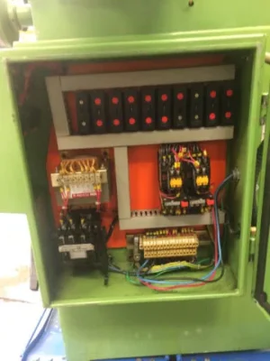
Here is a pic of the "brain" of the grinder:

There are a bunch of limit switches and electrically/mechanically controlled hydraulic valves that complement this panel. That is/was my primary reason for not running the machine with just 3 appropriately sized VFDs (one for each motor) and re-wiring the whole kit and caboodle.
It has external hydraulics (large tank) and coolant (small tank). In front is a de-mag that came with it.
Coolant and hydraulic motors did not run; here is why (hyd motor shown):
The bearing was full of shmoo. Luckily I don't think they ever ran them like that; it would have spun the bearings - but they were not. Replaced them and cleaned the inside; now they run like a top.
Here was the reason for a spindle vibration I got:
This is the "CJ" style urethane spider from the love-joy type coupling between the spindle and its drive motor. I have already glued the broken off ears back on (you can just see the one @ about 10'o-clock position). The spider is an odd-ball size, of course, and not available off the shelf.... Hence the drawing and the home made cutter.
Here is the cutter in use:
I made Delrin spiders first to see if my geometry was correct before I attempted it in rubber...
If rubber does not last, I now have an accurate part that I can make a mold from and cast a spider out of liquid urethane, if required.
Here is one installed on the motor side of the coupling:
Runs smoothly now (I did also replace the bearings in the motor, while I was at it).
Also made a couple knobs for the control panel (the alu ones in the bottom row) - they were missing; and a wheel arbor pulling tool:
All components of the grinder work, just not at the same time: I am waiting for my shop RPC so the machine can be powered properly with 3 phase, 220 V.
Here is a pic of the "brain" of the grinder:
There are a bunch of limit switches and electrically/mechanically controlled hydraulic valves that complement this panel. That is/was my primary reason for not running the machine with just 3 appropriately sized VFDs (one for each motor) and re-wiring the whole kit and caboodle.


